
Water control method after blast furnace cooling wall breakage

A stave damage technology, applied in the direction of cooling devices, etc., can solve the cooling capacity of stave damage, affect the life of the stave, burn the stave, etc., to achieve the effects of prolonging life, maintaining operation safety, and improving cooling efficiency

Inactive Publication Date: 2010-06-02
NANJING NANGANG IND DEV CO LTD
View PDF5 Cites 0 Cited by
  • Summary
  • Abstract
  • Description
  • Claims
  • Application Information

AI Technical Summary

Problems solved by technology

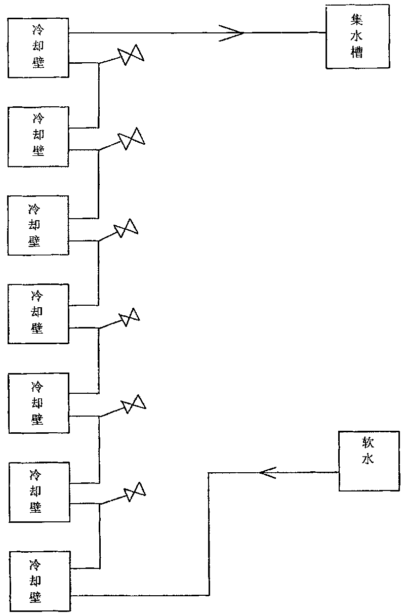
For the treatment of water leakage in the blast furnace stave, most blast furnaces used to temporarily control the water, such as figure 1 As shown, the soft water enters from the bottom of the system, and enters the sump from the top of the system. After it is really out of control, the air shutdown should be disconnected or blocked. This will cause the cooling wall to be damaged and the series of cooling channels will be cooled during water control. Insufficient quantity will affect the life of other staves
In addition, the amount of water control is an empirical value, there is no data, either too much water control or too little water control, resulting in overheating of the cooling wall when the water control is too large, and in serious cases, it will cause burning of the cooling wall; when the water control is small, the cooling water enters the furnace and causes furnace Unfavorable production phenomena such as fluctuating conditions and iron sputtering
Due to the above defects in the existing water control method after the blast furnace stave is damaged, the blast furnace body needs to replace the stave every four years on average

Method used


Image

  • Water control method after blast furnace cooling wall breakage
  • Water control method after blast furnace cooling wall breakage
  • Water control method after blast furnace cooling wall breakage

Examples


Embodiment 1

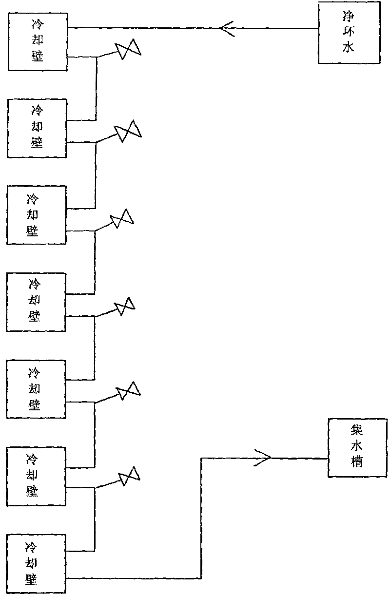
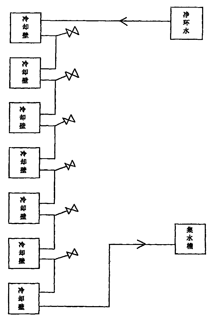
[0014] The schematic diagram of the water control method after the blast furnace stave is damaged in this embodiment is as follows figure 2 As shown, the water control method after the blast furnace stave is damaged is carried out according to the following steps:

[0015] (1) After determining that the stave is damaged, determine which string of staves the damaged point is located on;

[0016] (2) Replace the soft water of the series of cooling walls with clean ring water, and the clean ring water adopts the method of high inflow and low outflow, that is, the clean ring water enters from the uppermost part of the series of cooling walls and flows out from the bottom of the series of cooling walls , the water outlet of the net ring water is connected with the outside atmosphere;

[0017] (3) Adjust the water volume and flow rate to reduce the pressure in the channel of the series of staves, control the temperature of the outlet water and the gasp state to control the cooling...


PUM


Abstract

The invention relates to a method for controlling water in a metallurgical blast furnace, in particular to a method for controlling water after a cooling wall of the blast furnace is damaged. The method is carried out according to the following steps: (1) after the cooling wall is judged to be damaged, the bunch of the cooling wall in which a damaged point is positioned is determined; (2) soft water in the bunch of the cooling wall is changed into clean circulating water; the clean circulating water adopts a mode of high-in and low-out, that is the clean circulating water enters from the uppermost part of the bunch of the cooling cool and flows out from the lowermost part of the bunch of the cooling wall; and (3) the amount and the flow speed of the water are adjusted to reduce the pressure in a passage of the bunch of the cooling wall, the water effluent temperature and the breathing state are controlled so as to control the cooling strength of the bunch of the cooling wall and the amount of water entering the furnace. The method for controlling water after the cooling wall of the blast furnace is damaged can rapidly control the amount of water leaking into the furnace from the leaked cooling wall, avoid the phenomena of abnormality of the furnace situation, splashing on a taphole and the like, reduces the damping down and can fully cool a water controlling passage including the damaged cooling wall.

Description

technical field [0001] The invention relates to a water control method of a metallurgical blast furnace, in particular to a water control method after a blast furnace stave is damaged. Background technique [0002] Most modern blast furnace bodies are cooled by a soft water closed circulation system, and the water leakage treatment of the stave of this system has also become a recognized problem. For the treatment of water leakage in blast furnace staves, most blast furnaces used to temporarily control water, such as figure 1 As shown, the soft water enters from the bottom of the system, and enters the sump from the top of the system. When it is really uncontrollable, the air should be disconnected or blocked. This will cause the cooling wall to be damaged and the series of cooling channels will be cooled during water control. If the amount is not enough, it will affect the life of other staves. In addition, the amount of water control is an empirical value, there is no da...

Claims


Application Information

Patent Timeline
Patent Type & Authority Patents(China)
IPC IPC(8): C21B7/10
Inventor 杜卫中
Owner NANJING NANGANG IND DEV CO LTD
Learn More