Eureka AIR delivers breakthrough ideas for toughest innovation challenges, trusted by R&D personnel around the world.

Quick precise injection platform

A precise and fast technology, applied in the field of double-cylinder balanced injection platform structure, can solve the problem of high noise, achieve the effect of reducing the amount of oil return, reducing the speed of oil return, and solving the effect of excessive oil return pressure and speed

Inactive Publication Date: 2009-03-11
广东力劲塑机智造股份有限公司
View PDF0 Cites 1 Cited by
  • Summary
  • Abstract
  • Description
  • Claims
  • Application Information

AI Technical Summary

Problems solved by technology

[0003] In order to overcome the deficiencies of the prior art, the present invention provides a fast and precise injection platform structure, which can solve the problem of excessive noise caused by excessive oil return pressure and speed when the rodless piston cavity is injected at high speed

Method used


Image

  • Quick precise injection platform
  • Quick precise injection platform

Examples


Embodiment Construction

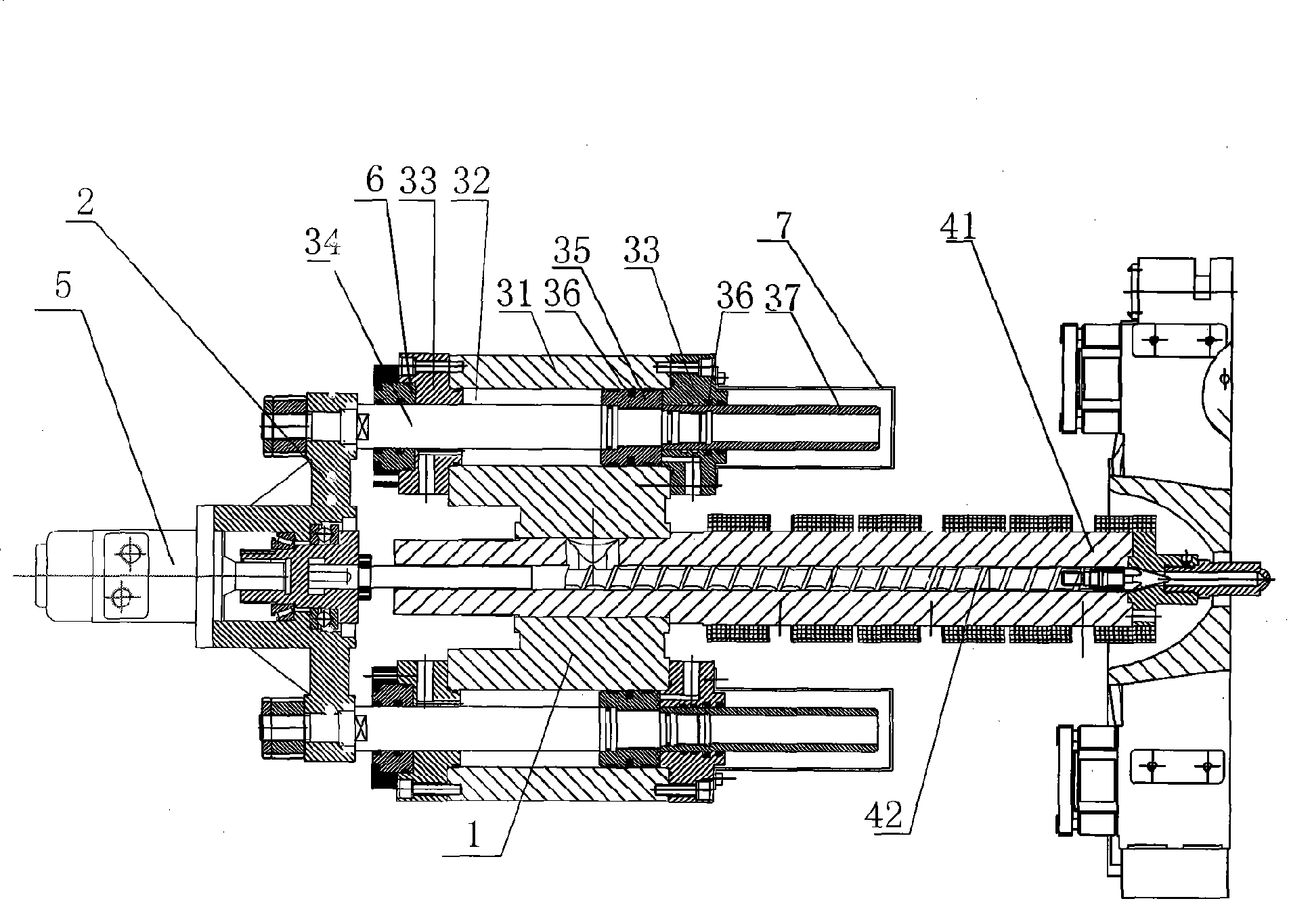
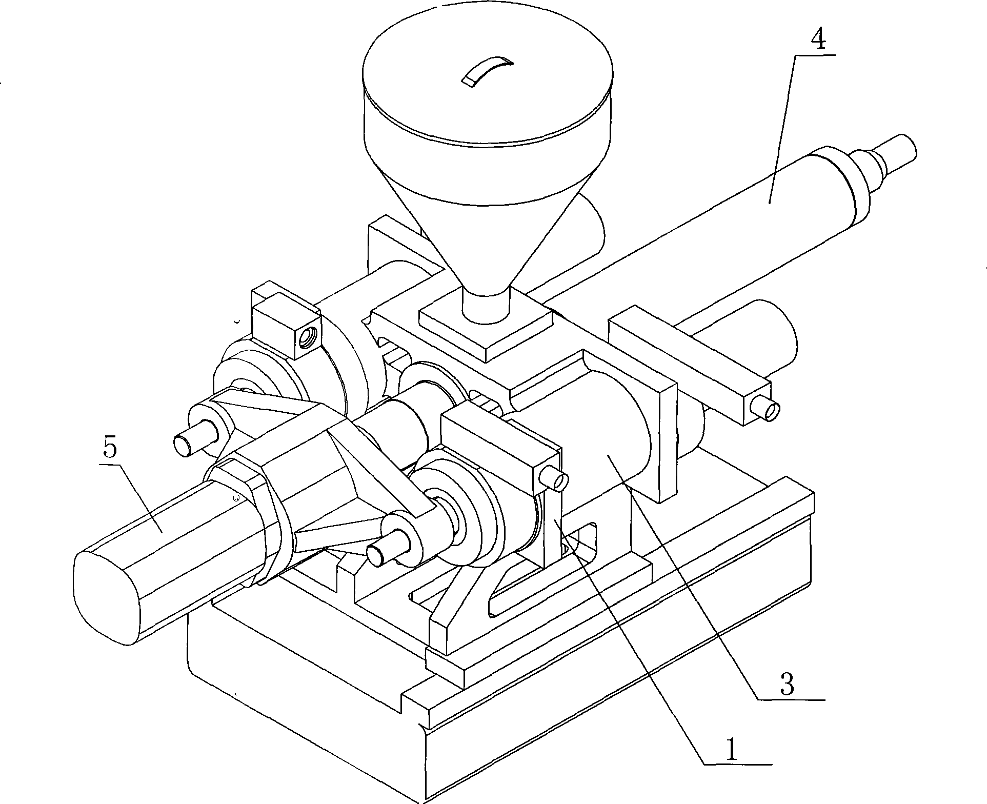
[0014] refer to figure 1 , figure 2 , the rapid and precise injection platform structure disclosed in the present invention includes an injection platform head plate assembly 1, an injection platform tail plate 2, two injection cylinder assemblies 3 and a melt cylinder assembly 4, wherein the injection cylinder assembly 3 is arranged on the injection platform head Both sides of the board assembly 1.

[0015] As shown in the figure, the injection cylinder assembly 3 used in the present invention includes a cylinder body 31, a piston chamber 32 is arranged in the cylinder body 31, a cylinder head 33 is installed at both ends of the cylinder body 31, and a piston rod is installed in the piston chamber 32 34. A piston 35 is fixedly installed on the piston rod 34, an oil seal 36 is installed between the piston 35 and the inner wall of the piston chamber 32, and the piston rod 34 passes through a cylinder head 33 at one end and is fixed on the injection tail plate 2.

[0016] The...


PUM


Abstract

The present invention discloses a fast precise injection table structure which comprises an injection table head plate component, a glue-injecting tail plate, two glue-injecting oil cylinder components and a glue-melting cylinder component. The glue-injecting oil cylinder components are arranged at two sides of the injection table head component. The glue-injecting tail plate is equipped with an oil motor. The glue-injecting oil cylinder component comprises a cylinder body, the inside of which is provided with a piston cavity which is equipped with a piston rod at the inside, the piston rod is fixedly equipped with a piston, and one end of the piston rod is fixed at the glue-injecting tail plate. The fast precise injection table structure is characterized in that the other side of the piston is equipped with a piston rod without a rod cavity, which extends outside the piston cavity. The additional piston rod of the fast precise injection table structure occupies a certain cubage of the piston cavity and reduces the hydraulic oil quantity of the piston cavity of the part correspondingly, and accordingly, the fast precise injection table structure can reduce the oil return quantity of the piston cavity of the part when glue is injected at a high speed, reduces the oil return speed and further solves the problem of too high noise caused by too high oil return pressure and speed when the original injection table injects the glue at a high speed.

Description

technical field [0001] The invention relates to an injection platform structure of an injection molding machine, in particular to a double-cylinder balanced injection platform structure. Background technique [0002] The injection table mechanism of the injection molding machine is composed of an injection table head plate assembly, an injection tail plate, two injection cylinder assemblies, a melt cylinder assembly and an oil motor. The traditional injection cylinder assembly includes a cylinder body, and a piston is arranged in the cylinder body. Cavity, a piston rod is installed in the piston cavity, a piston is fixedly installed on the piston rod, and one end of the piston rod is fixed on the rubber injection tail plate. The non-piston rod cavity of the injection cylinder will generate excessive noise due to excessive oil return pressure and speed during high-speed injection, which will cause noise pollution to the operating environment. Contents of the invention [0...

Claims


Application Information

Patent Timeline
Patent Type & Authority Applications(China)
IPC IPC(8): B29C45/53B29C45/54
Inventor 孙佩义刘国栋李治湘侯培善黄文辉杨珑冯光存
Owner 广东力劲塑机智造股份有限公司
Why Eureka
Eureka Blog
Learn More