
LED lighting kenel control system and method

A technology of LED controller and control system, applied in general control system, control/regulation system, computer control, etc., can solve problems such as inability to meet system requirements, single LED working mode, etc., and achieve the effect of improving the ability

Inactive Publication Date: 2012-03-14
HONG FU JIN PRECISION IND (SHENZHEN) CO LTD +1
View PDF0 Cites 0 Cited by
  • Summary
  • Abstract
  • Description
  • Claims
  • Application Information

AI Technical Summary

Problems solved by technology

Usually when the computer is shipped, the parameters of the LED have been set, such as the blinking mode and time delay of the LED, which makes the working mode of the LED relatively simple and cannot meet the requirements of the system under different working conditions.

Method used


Image

  • LED lighting kenel control system and method
  • LED lighting kenel control system and method
  • LED lighting kenel control system and method

Examples


Embodiment Construction

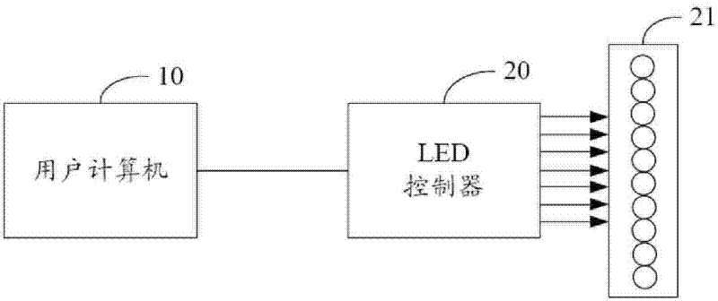
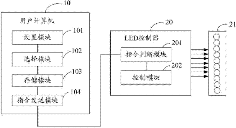
[0011] Such as figure 1 Shown is a system architecture diagram of a preferred embodiment of the LED light emitting pattern control system of the present invention. This system mainly comprises user computer 10, LED controller 20 and LED 21, and described user computer 10 is connected with described LED controller 20 through I2C (Inter-Integrated Circuit, internal integrated circuit) bus line, and described LED controller 20 and all The above LED 21 is connected. The user computer 10 provides a software interface for the user, through which the user can add LED information and set corresponding LED information for different computer operating states. Wherein, the LED controller 20 includes default LED information when leaving the factory. The LED information includes LED blinking mode and time delay, etc., and the computer running status includes normal status, overclocking status and warning status, etc. Through the software interface, the user can also set the operating mo...


PUM


Abstract

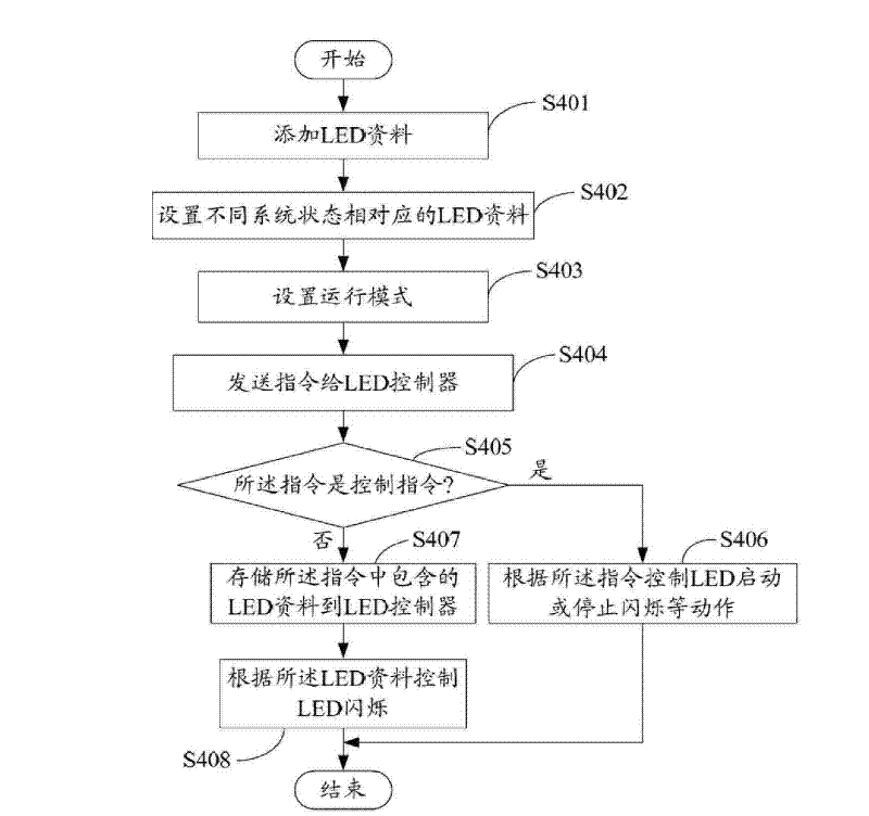
The invention provides a light emitting diode (LED) luminescence type control system and a method; wherein, the method comprises the steps as follows: LED data is added by a user computer; LED data corresponding to different computer running states and the running mode of the system are arranged; the running mode comprises a manual mode and an automatic mode; corresponding LED data under the manual mode is selected by the user computer; after the user computer receives the user instructions, the instructions are sent to the LED controller; the LED controller judges the type of the instructions; the LED controller reads the corresponding LED data according to the type of the instructions and controls the connected LED according to the LED data. The system and the method can automatically change the flashing type of the LED and improve the capability of displaying the running states of different computers by using the LED light.

Description

technical field [0001] The invention relates to a system and method for controlling an LED light emitting pattern. Background technique [0002] Currently, LEDs (Light Emitting Diodes, Light Emitting Diodes) are widely used in computers, such as LEDs on display card PCBs. Usually when the computer is shipped, the parameters of the LED have been set, such as the blinking mode and time delay of the LED, which makes the working mode of the LED relatively simple and cannot meet the requirements of the system under different working conditions. Contents of the invention [0003] In view of the above, it is necessary to provide an LED light emitting mode control system, which can automatically change the LED blinking mode according to the LED data corresponding to different computer operating states set by the user. [0004] In view of the above, it is also necessary to provide a method for controlling LED lighting patterns, which can automatically change the blinking mode of L...

Claims


Application Information

Patent Timeline
Patent Type & Authority Patents(China)
IPC IPC(8): G05B15/02F21S10/06H05B37/02F21W111/00F21Y101/02
CPCH05B33/0842H05B37/0254H05B45/30H05B47/18
Inventor 周竜毅张国伟杨志贤
Owner HONG FU JIN PRECISION IND (SHENZHEN) CO LTD
Learn More