Synchronous gear driven torque-resistance moment self-adapting automatic gear shift speed variator

A technology for driving torque and synchronizing gears, applied in the direction of gear transmission, belt/chain/gear, transmission, etc., it can solve the problems of engine or motor torque - small speed change, high transmission efficiency, limited bearing torque, etc. The effect of smooth gear and running process, improved transmission efficiency and smooth load change

Active Publication Date: 2011-04-27
SOUTHWEST UNIV
View PDF0 Cites 0 Cited by
  • Summary
  • Abstract
  • Description
  • Claims
  • Application Information

AI Technical Summary

Problems solved by technology

However, when CVTs are applied to small vehicles such as motorcycles, belt drives are basically used, and the carrying torque is limited. When the torque is large, the engine will lose rotation, which directly affects the power, economy and safety of electric vehicles.
High maintenance costs and shorter service life than ordinary transmissions
There are many existing patents on the improvement of automatic transmission and continuously variable transmission, but no substantive suggestions or improvements have been made to the above problems
[0004] Therefore, there is a need for an automatic automatic transmission, which can automatically shift gears without cutting off the driving force according to the change of driving resistance, and has high transmission efficiency, so as to solve the problem that the engine or electric motor torque-speed change is small and cannot be used on roads under complex conditions.

Method used


Image

  • Synchronous gear driven torque-resistance moment self-adapting automatic gear shift speed variator
  • Synchronous gear driven torque-resistance moment self-adapting automatic gear shift speed variator
  • Synchronous gear driven torque-resistance moment self-adapting automatic gear shift speed variator

Examples


Embodiment Construction

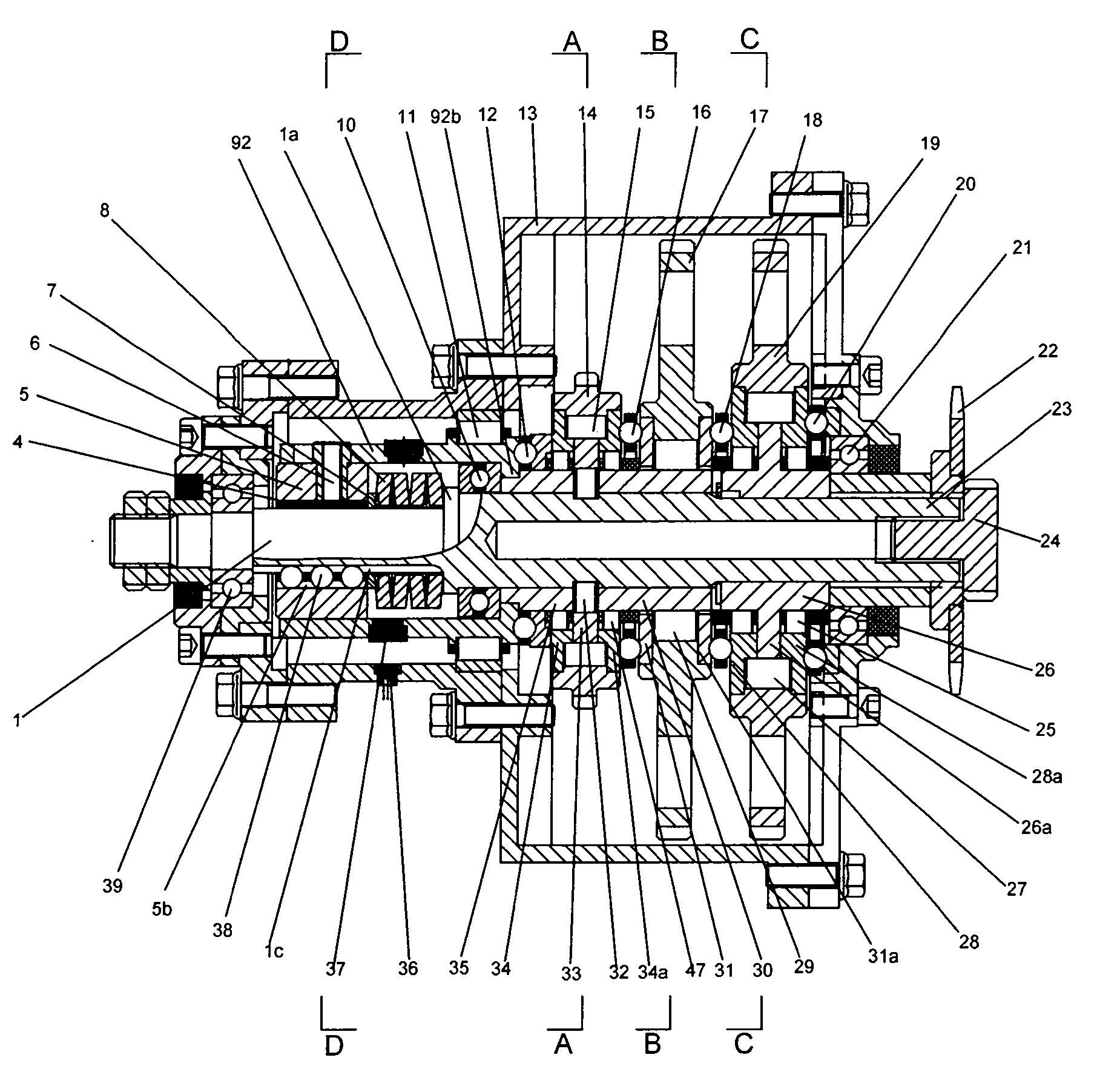
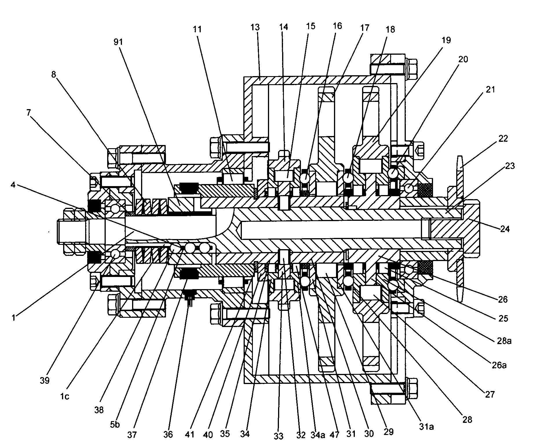
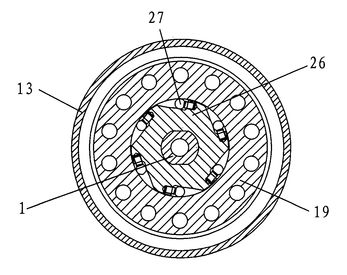
[0042] figure 1 It is a structural schematic diagram of the present invention, as shown in the figure: the driven camshaft 1 of this embodiment rotates clockwise when viewed from right to left to right during operation. The motor is arranged outside the casing, and the two ends of the driven camshaft 1 are in rolling fit with the casing 13 through the second radial rolling bearing 39 and the third radial rolling bearing 21, and the inner ring of the third radial rolling bearing 21 is set on the On the driven camshaft 1 , the right end of the driven camshaft 1 protrudes from the casing 13 and the sprocket 22 is fixedly matched with the sprocket 22 through bolts 24 .

[0043] Such as figure 1 As shown, the synchronous gear driving torque-resistance torque adaptive automatic shift transmission of the present invention includes the fast gear cam ejector gear overrunning clutch and the slow gear overrunning clutch synchronous gear mechanism arranged on the driven camshaft 1, and t...


PUM


Abstract

The present invention discloses a synchronous gear-driven torque-resistance torque self-adaptive automatic shift transmission, and comprises a box body, a driven cam shaft, a high gear cam push rod type gear overrunning clutch, a low gear overrunning clutch synchronous gear mechanism and a variable speed spring self-adaptive annular axial cam mechanism; wherein, the high gear cam push rod type gear overrunning clutch, the low gear overrunning clutch synchronous gear mechanism and the variable speed spring self-adaptive annular axial cam mechanism are arranged on the driven shaft. Because of the arrangement of two groups of slow gear overrunning clutch synchronous gear structures, the present invention not only realizes the self-adaptive automatic gear shifting for speed change along with the change of the running resistance with the driving force not to be cut off, but also can not lead to pause phenomena in the gear shifting process of the vehicle, thus the transmission efficiency isimproved; the running resistance is transmitted to the variable speed spring self-adaptive annular axial cam mechanism; the compression of the spring is maintained; and the preset invention realizes the stable switching between the gear shifting and the running. The gear shifting process is stable and no pause occurs; the gear directly meshes with the transmission shaft; and the transmission efficiency is high.

Description

technical field [0001] The invention relates to a transmission of a motor vehicle or mechanical power equipment, in particular to a synchronous gear drive torque-resistance torque adaptive automatic shift transmission. Background technique [0002] In the prior art, electric vehicles, motorcycles, and electric bicycles basically directly control the current or the speed of the throttle through the speed control handle or the accelerator pedal, or use the manual mechanical automatic transmission mechanism to realize the speed change. The operation of the handle or the accelerator pedal depends entirely on the driver's operation, which often results in a mismatch between the operation and the driving conditions, causing the engine to stall or the motor to run unstable and stalled. [0003] In the prior art, there are many types of transmissions for electric vehicles, motorcycles, and electric bicycles, but they are inseparable from each other. The transmissions mainly include ...

Claims


Application Information

Patent Timeline
Patent Type & Authority Patents(China)
IPC IPC(8): F16H3/08F16H59/00F16H61/00
Inventor 薛荣生林毓培郝允志
Owner SOUTHWEST UNIV
Why Eureka
Try Eureka