
Combined magnetic force separating mechanism for removing iron dust in plastic

A magnetic separation and composite technology, applied in the direction of magnetic separation, solid separation, chemical instruments and methods, etc., can solve the problems of small effective working surface, iron filings do not have the separation function, can not achieve fast and effective, etc.

Inactive Publication Date: 2009-02-25
上海金玺实验室有限公司
View PDF0 Cites 12 Cited by
  • Summary
  • Abstract
  • Description
  • Claims
  • Application Information

AI Technical Summary

Problems solved by technology

[0006] However, due to the round rod shape of the magnetic rod itself, the effective working surface for separating iron filings is very small, and it does not have the separation function for larger particles or massive iron filings. When dealing with a large number of products, it still cannot achieve fast and effective. effects and may require repeated magnetic separations to achieve higher quality requirements

Method used


Image

  • Combined magnetic force separating mechanism for removing iron dust in plastic
  • Combined magnetic force separating mechanism for removing iron dust in plastic
  • Combined magnetic force separating mechanism for removing iron dust in plastic

Examples


Embodiment Construction

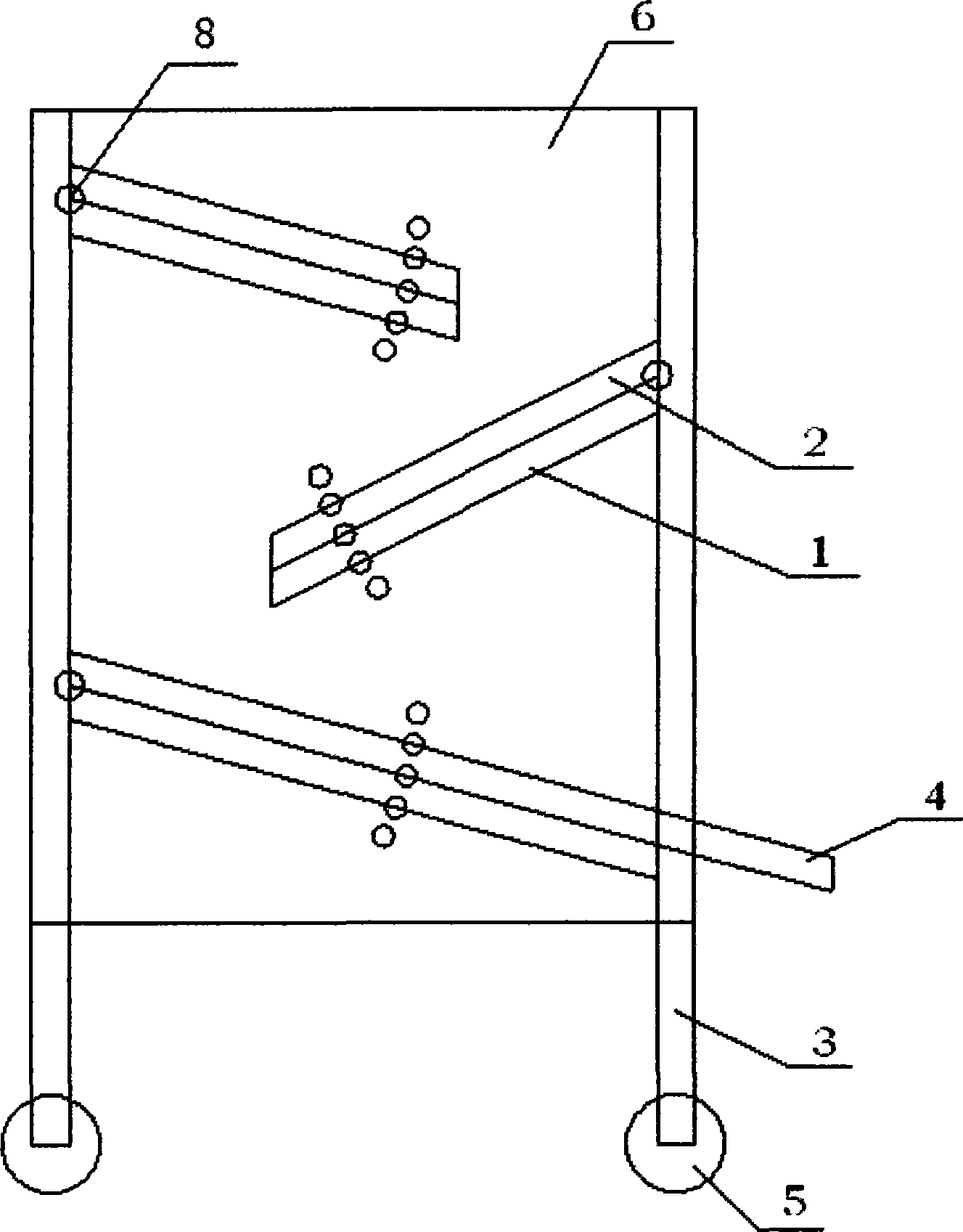
[0021] This composite magnetic separation device for removing iron scraps from plastics consists of five parts: a permanent magnet block, a separation plate, a support frame, a baffle plate, and a discharge port. It is characterized in that:

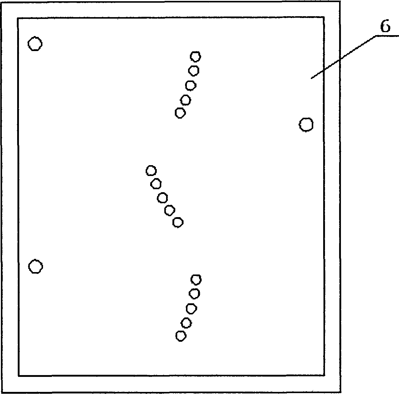
[0022] A. The separation plate 2 embedded with the permanent magnet block 1 is arranged on the support frame 3 from top to bottom in a dislocation shape from top to bottom by the screw rod 8, until the bottom separation plate is connected with the discharge port 4;

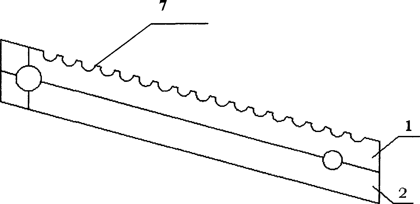
[0023] B. The surface of the separation plate 2 is provided with an adsorption groove 7 perpendicular to the material flow direction.

[0024] The adsorption groove 7 is a continuous through groove or a discontinuous pit.

[0025] The separation plate 2 is made of magnetically permeable material.

[0026] The permanent magnet block is made of permanent magnet material, and can be connected with the separation plate by screw thread or snap connection, or can be connected by ...


PUM


Abstract

The invention relates to a plastic compound magnetic separation device for removing iron chips which consists of five parts of a permanent magnetic block, separating plates, a support frame, a baffle and a discharge hole. The device is characterized in that: A. the separating plates (2) which are embedded with the permanent magnetic block (1) are arranged on the support frame (3) from up to down in left-right dislocation state by a screw (8) until the separating plate at the bottommost layer is connected with the discharge hole (4); B. the surface of the separating plates (2) is provided with an absorption tank (7) which is vertical to the flowing direction of materials. Due to the composite rough separating plates with large area in different directions, large metal chips even metal blocks can be separated effectively. Plastic particles have certain elasticity and can eject and move downwards when being in contact with the surfaces of the separating plates. Drop pits on a plane can ensure more effectively than drop pits on a traditional magnetic rod that absorbed iron chips cannot be rolled into the solid flow of the plastic particles again. One time or a plurality of times of over-magnetic effect can be effectively guaranteed in the production application. The production efficiency is obviously improved.

Description

technical field [0001] The invention relates to a device for separating iron filings mixed in non-magnetic materials, in particular to a composite magnetic separation device for removing iron filings from plastics, belonging to mechanical accessories. Background technique [0002] No matter in the plastic blending modification industry or waste plastic recycling granulation, and before plastic injection molding processing, it may be necessary to separate metal shavings from plastic particles. Because in the production and processing of plastic particles, due to many factors such as equipment wear, special production technology, unpredictable human factors, etc., there are some metal powders and fragments in the material particles, which have a great impact on the quality of plastic particles and plastics. Injection molding is very unfavorable. [0003] At present, it is widely used in the industry to use permanent magnet magnetic rods to adsorb metal iron filings in plastic...

Claims


Application Information

Patent Timeline
IPC IPC(8): B03C1/02
Inventor 杨定吉甫
Owner 上海金玺实验室有限公司
Learn More