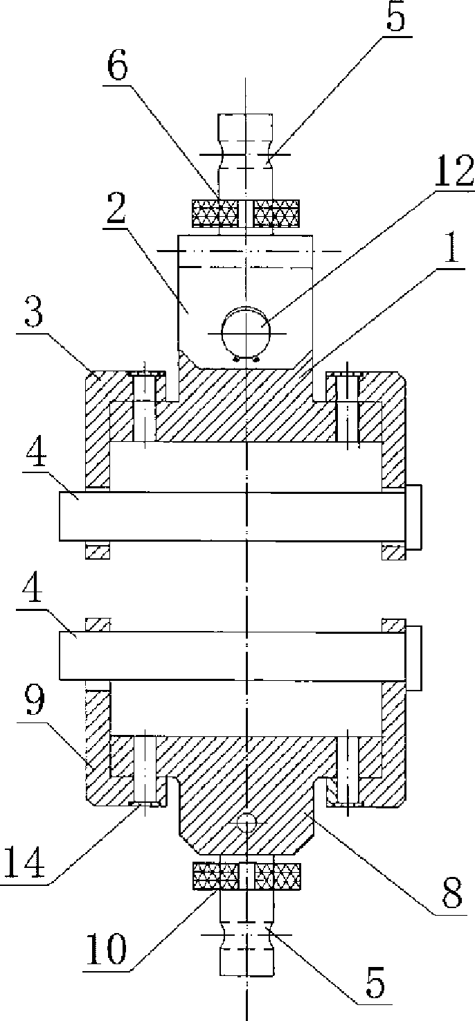
Special fixture for curtain wall door and window metal heat insulation section bar tensile test
A technology of tensile test and special fixture, which is applied in the direction of analyzing materials, measuring devices, instruments, etc., can solve the problems of the test piece falling to one side, the force is not vertical, and the fixture model is not universal, so as to achieve convenient and fast use and high performance. reliable effect
- Summary
- Abstract
- Description
- Claims
- Application Information
AI Technical Summary
Problems solved by technology
Method used
Image
Examples
Embodiment 1
[0033] Embodiment one sees Figure 1-4 As shown, this special fixture for the tensile test of metal insulation profiles for curtain walls, doors and windows includes an upper clamp 1, a lower clamp 8, an upper clamp 3 and a lower clamp for clamping the profile. The jack that fits the bolt, the upper chuck 1 is an inverted T shape, and its upper part is connected to a hanger 2 through the pin shaft and the clamp 12. The top of the hanger 2 is connected with an upper screw and an adjustment handwheel 6, and the upper chuck 1 A pair of replaceable inverted L-shaped upper splints 3 are connected to the two shoulders of the upper splint 3. There is a triangular jack 7 on the upper splint 3. The triangular jack 7 is mated with the triangular latch 4. One end of the triangular latch 4 has a pin head. The cross section of the rod is a triangle corresponding to the triangle jack, the lower chuck 8 is T-shaped, the bottom of which is connected with the lower screw rod and the adjusting ...
Embodiment 2
[0038] Embodiment two see Figure 7 , the above-mentioned upper splint, lower splint and bolt have the following replacement parts: the upper splint and the lower splint with circular jacks, the circular bolt 11 matched therewith, one end of the circular bolt has a pin head, and the cross-section of the rod is a circle corresponding to a circular jack. A profile 16 is connected between the upper splint and the lower splint through a circular bolt.
Embodiment 3
[0039] Embodiment three see Figure 8 , the above-mentioned lower clamping plate is a Z-shaped lower clamping plate 15 . A profile 16 is connected between the upper splint and the Z-shaped lower splint 15 .
[0040] Working process of the present invention:
[0041] 1. Turn on the testing machine, turn on the computer and enter the operation interface. (preheat for 5 minutes)
[0042] 2. Put the upper chuck of the fixture into the beam of the testing machine and fix it with a bolt. There are movable joints on the upper side of the upper clamp so that the upper and lower clamps are on the same straight line when the heat insulation profile is pulled.
[0043] 3. Put the lower chuck of the fixture into the base and fix it with a bolt. The upper and lower fixtures should be installed in parallel on the same line and parallel to each other.
[0044] 4. Put one end of the heat insulation profile into the upper fixture and fix it with a triangular bolt. Due to the different ty...
PUM
 Abstract
Description
Claims
Application Information
 - R&D Engineer
- R&D Manager
- IP Professional
- Industry Leading Data Capabilities
- Powerful AI technology
- Patent DNA Extraction
Browse by: Latest US Patents, China's latest patents, Technical Efficacy Thesaurus, Application Domain, Technology Topic, Popular Technical Reports.
© 2024 PatSnap. All rights reserved.Legal|Privacy policy|Modern Slavery Act Transparency Statement|Sitemap|About US| Contact US: help@patsnap.com


