Carroll fluid machine
A technology of fluid machinery and casing, which is applied in the field of Carroll fluid machinery, can solve the problems of difficult medium import and export processing, inconvenient production organization, complex casing shape, etc., to improve processing accuracy and efficiency, save maintenance costs, Processing simple effect
- Summary
- Abstract
- Description
- Claims
- Application Information
AI Technical Summary
Problems solved by technology
Method used
Image

Examples
Embodiment 1
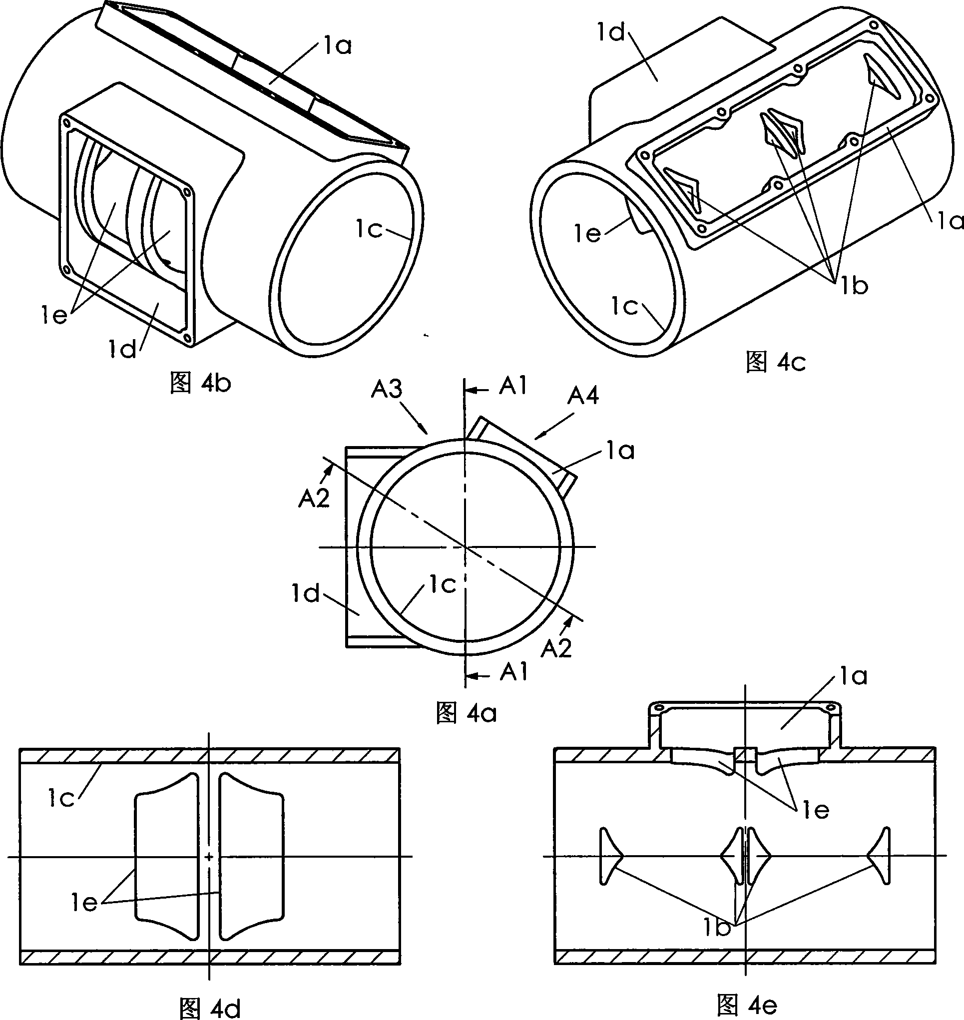
[0076] Referring to Figures 6a-6e, in combination with Figures 4a-4e and Figure 5, the medium inlet and outlet part 8 of the present invention is in the shape of a straight wall cylinder, and the second medium suction port 8d and the second medium discharge port 8b are provided on the cylinder wall ; The second medium suction port 8d and the second medium discharge port 8b are completely identical in size, shape and orientation to the first medium suction port 1e and the first medium discharge port 1b on the housing 1 shown in FIGS. 4a to 4e. same. The inlet and outlet parts 8 of the present invention are installed in the inner cavity of the housing 1 according to the corresponding circumferential orientation, and the second medium suction port 8d and the second medium discharge port 8b on it just meet the working chambers of the cylinders on the fluid machine cylinder 2. 2b media suction and discharge use requirements.
[0077]Referring to Figures 7a-7e, combined with Figure...
Embodiment 2
[0080] Referring to Figures 9a-9b, combined with Figures 4a-4e, the only difference between the two shell structure schemes is that the first medium suction port 1e on the shell 1 of this embodiment is a large octagonal-like hole, and the octagonal-like The large holes correspond to the two adjacent cylinder working chambers 2b on the cylinder body 2 at the same time. In fact, it is equivalent to connecting the two isosceles trapezoidal first medium suction ports 1e corresponding to the two cylinder working chambers 2b on the cylinder body 2 respectively on the housing 1 shown in Fig. The machining of the first medium suction opening 1e of the body 1 can be suitably simplified.
[0081] Referring to Figures 10a-10b, in combination with Figures 6a-6e and Figures 9a-9b, the second medium suction port 8d and the second medium discharge port 8b on the inlet and outlet parts 8 of this embodiment are the same as those of the housing 1 shown in Figures 9a-9b. The first medium suctio...
Embodiment 3
[0084] refer to Figures 12a-12b , combined with Figures 4a to 4e, the only difference between the two housing structures is that the first medium suction port 1e on the housing 1 of this embodiment is four symmetrically arranged right-angled trapezoidal holes, which are located at the same length of the inlet and outlet parts 8 The two right-angle trapezoidal second suction ports on the section correspond to the same cylinder working chamber 2b on the cylinder block 2 . The long bases of the two pairs of right-angled trapezoidal holes are adjacent and parallel, perpendicular to the generatrix of the cylinder wall of the inlet and outlet part 8, and tangent to or adjacent to the corresponding cylinder hole 2b on the cylinder body 2. In fact, it is equivalent to dividing the two isosceles trapezoidal first suction ports on the housing 1 shown in Fig. 8. Each part of the opening area on the cylinder wall is not large, which helps to ensure that the rigidity of the cylinder body...
PUM
 Abstract
Description
Claims
Application Information
 - R&D
- Intellectual Property
- Life Sciences
- Materials
- Tech Scout
- Unparalleled Data Quality
- Higher Quality Content
- 60% Fewer Hallucinations
Browse by: Latest US Patents, China's latest patents, Technical Efficacy Thesaurus, Application Domain, Technology Topic, Popular Technical Reports.
© 2025 PatSnap. All rights reserved.Legal|Privacy policy|Modern Slavery Act Transparency Statement|Sitemap|About US| Contact US: help@patsnap.com