
On-line real-time optical fiber grating fire monitoring system

A fiber grating and monitoring system technology, which is applied to electric fire alarms, measuring devices, measuring heat, etc., can solve the problems of inability to predict the temperature change process of disaster prevention sites, expensive demodulators, and limited application range, etc. problem, to achieve the effect of online real-time rapid fire monitoring, fast demodulation speed and low cost

Inactive Publication Date: 2009-02-11
山西关铝集团有限公司
View PDF0 Cites 10 Cited by
  • Summary
  • Abstract
  • Description
  • Claims
  • Application Information

AI Technical Summary

Problems solved by technology

The price of the temperature-sensing cable is relatively low (about 50 yuan / m), but it cannot be positioned or predicted the temperature change process of the disaster prevention site
Developed in recent years, the use of distributed optical fiber temperature sensors and quasi-distributed optical fiber temperature sensors (mainly fiber grating type and optical fiber Fab type) is used as a temperature-sensitive fire detector for linear fire monitoring temperature-sensing cables. It can be used online in real time Forecast the change of temperature, and can set the alarm temperature in a large temperature range. It is an intrinsically safe linear temperature-sensitive fire detector. It has been successfully applied in the power industry, petrochemical enterprises and civil engineering, but the price of the demodulator Expensive, limited range of applications

Method used


Image

  • On-line real-time optical fiber grating fire monitoring system

Examples


Embodiment Construction

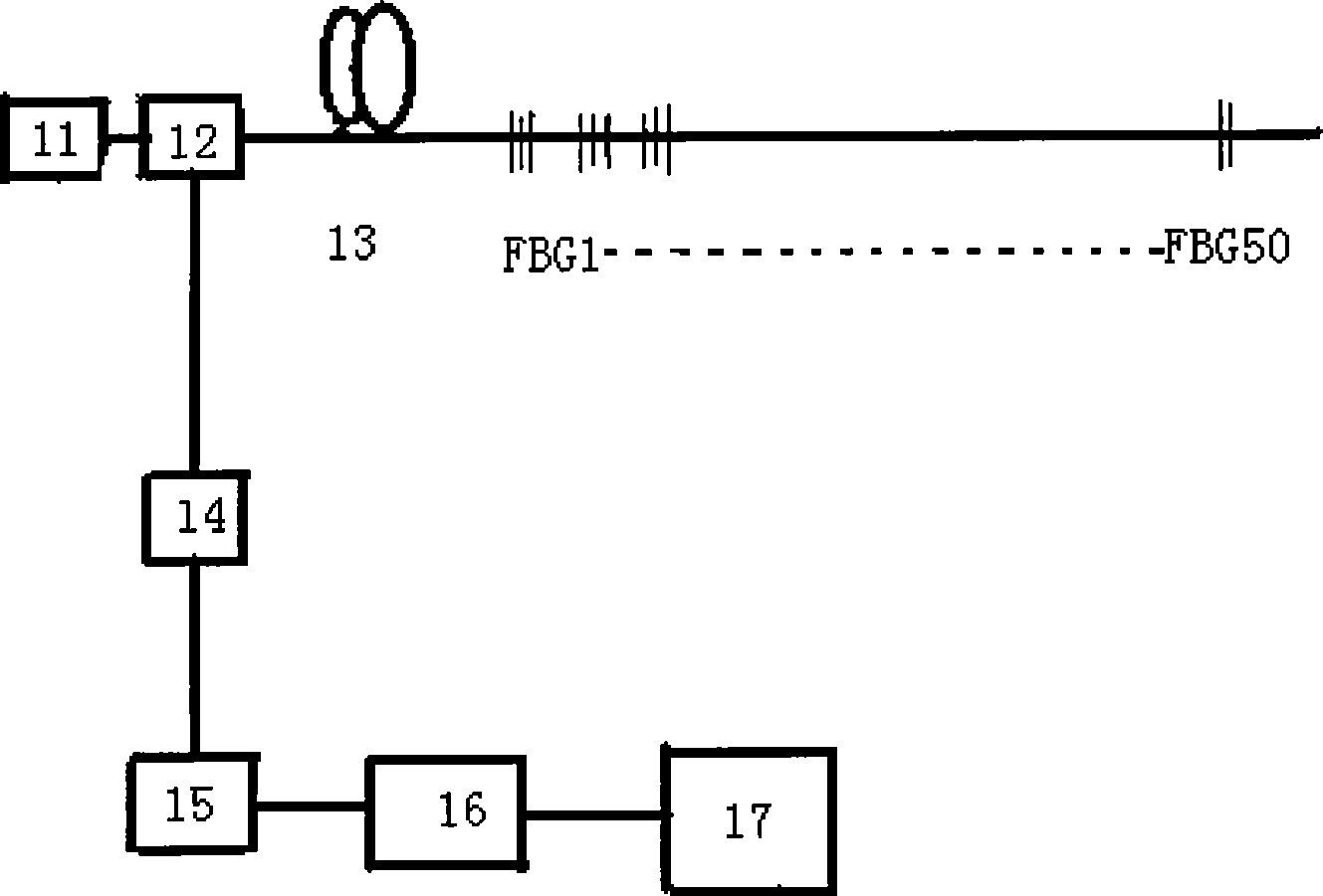
[0012] With reference to Fig. 1, on-line real-time fiber grating fire monitoring system of the present invention comprises laser diode 11, optical fiber circulator 12 with pigtail, temperature-sensitive optical cable 13, optical fiber coarse wavelength division multiplexing demodulator 14, photodetector 15, digital Signal processor 16 and display or alarm 17, the input end of optical fiber circulator 12 links to each other with the laser diode 11 of band pigtail, and a port of optical fiber circulator 12 links to each other with one end of temperature-sensitive optical cable 13, on temperature-sensitive optical cable 13 It is connected with n fiber grating temperature-sensitive fire detectors (18) of the same wavelength, n is a positive integer, the backscattered light and reflected light generated by the temperature-sensitive optical cable 13 enter through the fiber optic circulator 12, and the fiber grating sensor caused by temperature changes The main wavelength displacement...


PUM

PropertyMeasurementUnit
wavelengthaaaaaaaaaa
reflectanceaaaaaaaaaa
wavelengthaaaaaaaaaa

Abstract

The invention discloses an online real-time optical fiber grating fire monitoring system which is implemented based on the coarse wavelength division multiplexing (CWDM) demodulation technique, the optical time-domain analysis technique and the optical fiber grating temperature measurement technique. The system comprises an optical fiber circulator, wherein the input terminal of an optical fiber circulator is connected with a laser diode with a tail fiber, and the output terminals of the optical fiber circulator are connected in sequence with a coarse wavelength division multiplex demodulator; a photoelectric detector connected with a digital signal processor; a temperature-detecting optical cable connected with the other port of the optical fiber circulator; optical fiber grating temperature-sensitive fire detectors numbering n of the same wavelength connected to the temperature-detecting optical cable; and a display device or an alarm connected with the signal output terminal of the digital signal processor. N is a positive integer. The fire monitoring system has the advantages of low cost, high resolution and high demodulation speed and is better in performance-price-ratio than the prior fire-control temperature-sensitive cables and other temperature-sensitive optical cables.

Description

technical field [0001] The invention relates to a fire monitoring system, in particular to an online real-time optical fiber grating fire monitoring system. Background technique [0002] For a long time, in the field of fire protection technology and engineering at home and abroad, linear temperature-sensing cables are mainly used as linear temperature-sensing fire detectors. The temperature-sensing cable is a two-core cable designed with the "on / off" principle. When the built-in two-core wire is heated and dissolved at the preset temperature, a short circuit will be formed and an alarm will be issued. The price of the temperature-sensing cable is relatively low (about 50 yuan / m), but it cannot be positioned, nor can it predict the change process of the temperature at the disaster prevention site. Developed in recent years, the use of distributed optical fiber temperature sensors and quasi-distributed optical fiber temperature sensors (mainly fiber grating type and optical ...

Claims


Application Information

Patent Timeline
Patent Type & Authority Applications(China)
IPC IPC(8): G08B17/06G01K11/32G01K11/3206
Inventor 张在宣董新永龚华平张淑琴
Owner 山西关铝集团有限公司
Learn More