


Quick Research
Generate reliable direction feasibility study reports for your R&D in just a few steps.

Technical Q&A
Discover and master advanced knowledge NOW. Basics, ideas, possibilities, all at once.

Find Solutions
As an expert in R&D theories, this can generate solutions to your technical problems instantly.

Evaluate Feasibility
Analyze your overall solution with one click, know your potential R&D risks in advance.

Monitor Landscape
Get weekly tech updates, stay abreast of the latest tech innovations and key insights.
Batch money drawing machine and batch money drawing method
A cash machine and the same technology are applied to the complete banking system, devices that accept coins, instruments, etc., to achieve the effects of alleviating queuing withdrawals, improving utilization rates, and saving maintenance costs
- Summary
- Abstract
- Description
- Claims
- Application Information
AI Technical Summary
Problems solved by technology
Method used
Image

Examples
no. 1 example
[0071] Such as Figure 2A As shown, the system of this embodiment mainly includes a body 6 and a card reading device (not shown in the figure) installed in the body, a control device (not shown in the figure), a payment device 3, a coin guide channel 4 and a cash output device 5. Wherein the baffle plate adjacent to the banknote dispensing device 5 is the baffle plate of the user's operation surface below the body.
[0072] There can be one or more payment devices 3, and 2 of them arranged side by side are shown in the figure. The bundle of banknotes is extracted and sent to the entrance of the coin guide channel 4.
[0073] The inlet and the outlet of the coin guide channel 4 are respectively connected to the payment device 3 and the cash output device 5 , forming a passage for bundled banknotes to slide from the payment device 3 to the cash output device 5 .
[0074] The banknote output device 5 is installed at the banknote outlet, and can accommodate bundled banknotes. A...
no. 2 example
[0111] Such as Figure 13 with 14 As shown, the system of this embodiment also includes a body 6' and a card reading device (not shown in the figure) installed in the body, a control device (not shown in the figure), a payment device 3', a coin guide channel 4' and Cash out device 5'. The overall functions and connections of the above devices are also the same as those in the first embodiment, and will not be repeated here.
[0112] On concrete structure, banknote output device 5' and ATM body 6' are also identical with the first embodiment, and payment device 3' and guiding coin channel 4' are different from the first embodiment. In addition, there are some differences in the method of withdrawal. It will be described in detail below.
[0113] The sectional view of payment device 3' of the present embodiment is as Figure 15 As shown, it can be referred to the Chinese patent No. 02245909.X titled "A Kind of Intelligent Batch Payment Device", which is the same as the stru...
no. 3 example
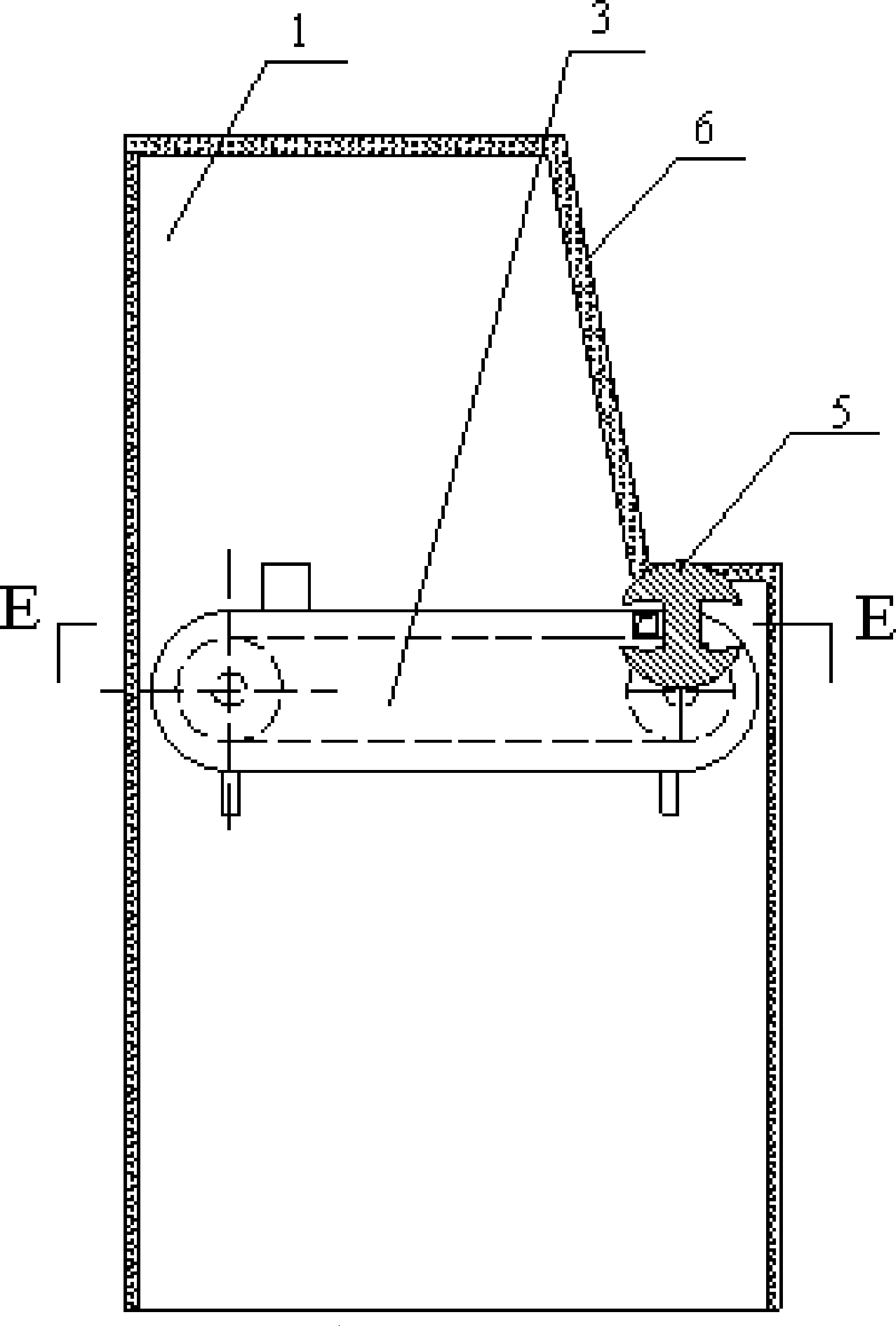
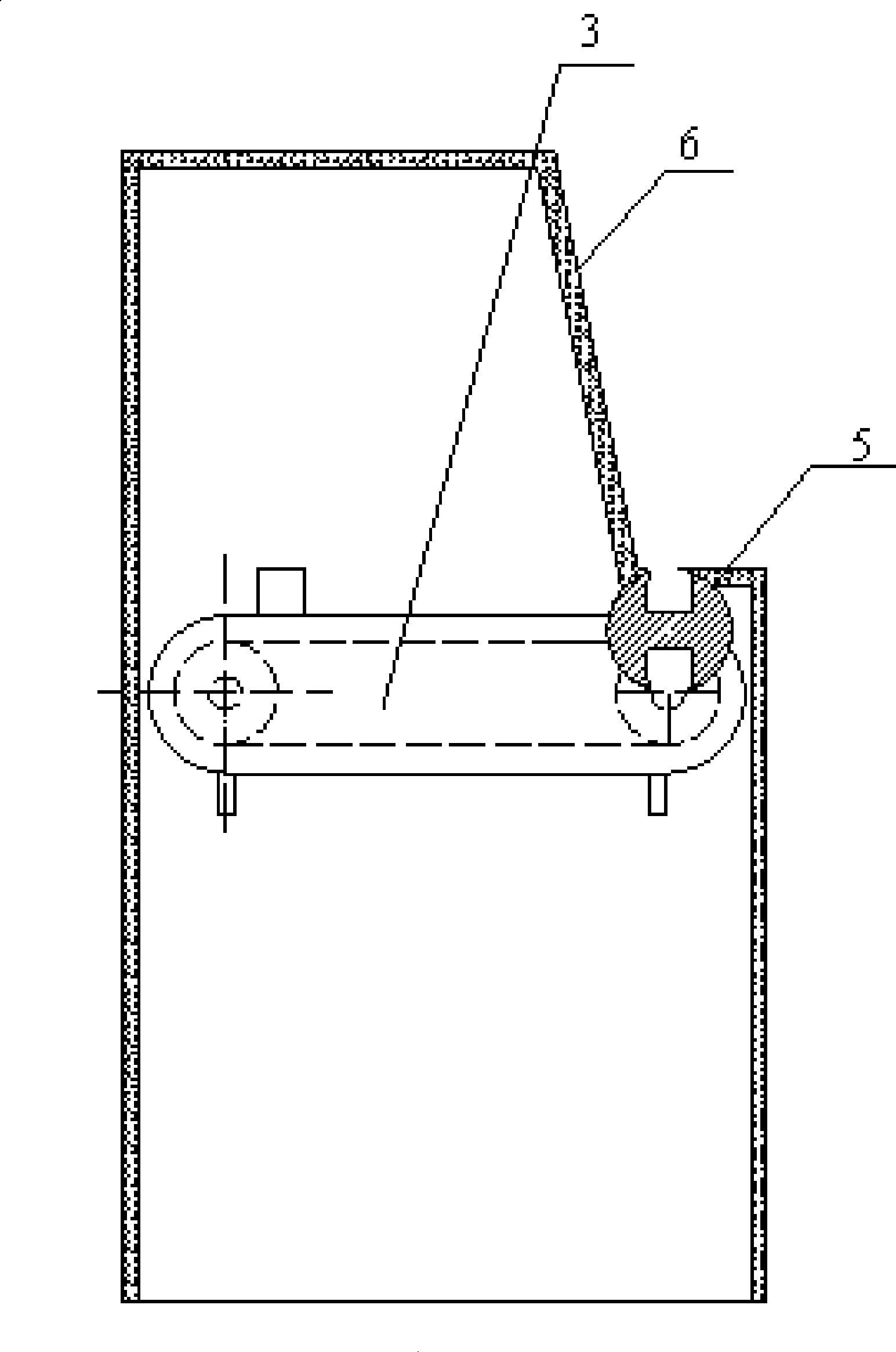
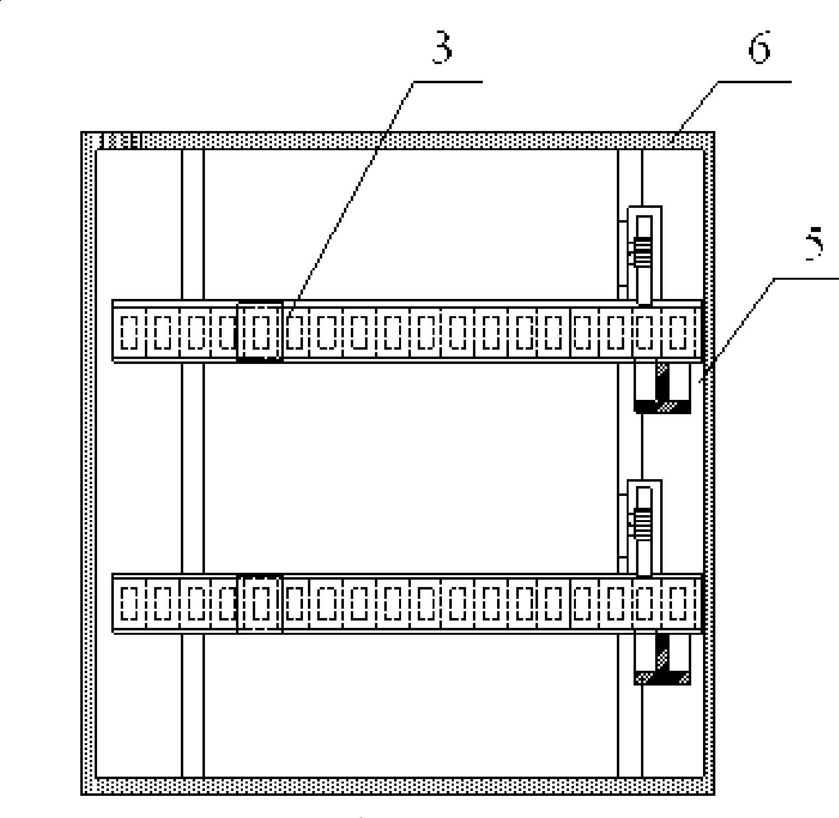
[0133] The structure of this embodiment batch cash machine is as Figure 1A , Figure 1B with Figure 1C As shown, the main difference between this batch cash dispenser and the first embodiment is that there is no coin guide channel, and the bundled banknotes pushed out by the payment device can directly fall into the storage slot of the banknote dispensing device.
[0134] As shown in the figure, the rotating body of the banknote output device 5 is placed horizontally, the end of the storage slot on it is opened, and it is placed close to the bundled banknote push-out opening on the payment device 3. If the gap is less than 2mm, the push-out mechanism (not shown) It is located on the other side of the payment device 3 and corresponds to the push-out port. In addition, the upper part of the cabinet body is a slanted plate, and the lower part is a vertical plate. The inclined surface and the vertical surface are connected by a flat plate, and the cash outlet is located on the ...
PUM
 Abstract
Description
Claims
Application Information
 - R&D Engineer
- R&D Manager
- IP Professional
- Industry Leading Data Capabilities
- Powerful AI technology
- Patent DNA Extraction
Browse by: Latest US Patents, China's latest patents, Technical Efficacy Thesaurus, Application Domain, Technology Topic, Popular Technical Reports.
© 2024 PatSnap. All rights reserved.Legal|Privacy policy|Modern Slavery Act Transparency Statement|Sitemap|About US| Contact US: help@patsnap.com