
Light guide assembly and light source module

A technology of light guide components and light source modules, which is applied to optical elements, light guides, optics, etc., and can solve the problem of uneven distribution of outgoing light.

Inactive Publication Date: 2012-03-21
ASIA OPTICAL CO INC
View PDF0 Cites 0 Cited by
  • Summary
  • Abstract
  • Description
  • Claims
  • Application Information

AI Technical Summary

Problems solved by technology

[0005] The technical problem to be solved by the present invention is to provide a light guide assembly and a light source module that can uniformly distribute the emitted light energy in view of the defect of uneven distribution of emitted light in the prior art

Method used


Image

  • Light guide assembly and light source module
  • Light guide assembly and light source module
  • Light guide assembly and light source module

Examples


Embodiment Construction

[0016] The foregoing and other technical content, features and effects of the rotating light-emitting device of the present invention will be clearly understood in the following detailed description of three preferred embodiments with accompanying drawings.

[0017] Before the present invention is described in detail, it should be noted that in the following description, similar components are denoted by the same numerals.

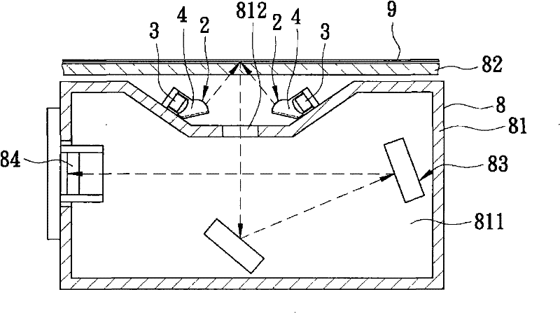
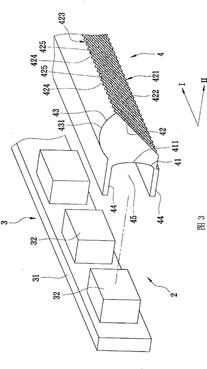
[0018] refer to figure 2 , image 3 , is the first preferred embodiment of the light guide assembly 4 and the light source module 2 of the present invention, and illustrates that the first preferred embodiment is installed on the scanning device 8 . The scanning device 8 includes a main body 81 having a reflection chamber 811 and an entrance 812 communicating with the reflection chamber 811, a light-transmitting plate 82 installed above the main body 81 for placing documents 9 to be scanned, and arranged on the main body 81. The reflective mirror group ...


PUM


Abstract

The invention relates to a light guide component and a light source module, comprising a light guide component and a light group; wherein, the light guide component comprises an incidence surface, a reflection surface and an emittance surface; the incidence surface is extended along the length direction and is provided with the incident curvature in the section direction; the reflection surface is provided with a diffraction part arranged along the length direction, and a reflection layer coated on the diffraction part; the emittance surface is extended along the length direction and has the emittance curvature in the section direction; in addition, the light group comprises a plurality of LED lights which are alternately arranged along the length direction; when the rays emitted by the LED lights of the light group are reflected by the diffraction part of the light guide component, the reflected rays can be diffused and evenly emitted out through the emittance surface.

Description

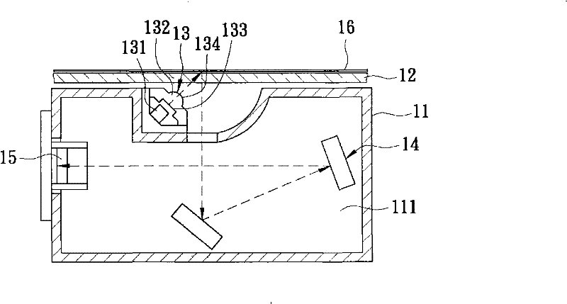
technical field [0001] The invention relates to a scanning device, in particular to a light guide assembly and a light source module. Background technique [0002] In recent years, in order to solve the problem of long warm-up time of the traditional cold cathode fluorescent lamp (CCFL) light source module, the scanning device has continuously developed and used light-emitting diodes (LEDs) as a new generation of light source, which has become a new type of light source in the industry. A necessary trend. [0003] Such as figure 1 Shown is a conventional scanner 1 using LED lamps as the light source, which includes a main body 11 , a light-transmitting plate 12 , a light source module 13 , mirror sets 14 , and an image capture unit 15 . Wherein, the main body 11 includes a reflective chamber 111; the transparent plate 12 is installed above the main body 11; the light source module 13 is installed on the main body 11 and interposed between the transparent plate 12 and the m...

Claims


Application Information

Patent Timeline
Patent Type & Authority Patents(China)
IPC IPC(8): G02B6/00G02B17/00H04N1/04
Inventor 林献琪张恒祥洪文郎邓孔欣
Owner ASIA OPTICAL CO INC
Learn More