Electrical machine, in particular synchronous motor, with redundant stator windings

A stator winding and stator technology, applied in the direction of AC motor control, shape/style/structure of winding conductors, electric components, etc., to achieve the effect of saving space

Active Publication Date: 2011-04-06
SIEMENS AG
View PDF6 Cites 0 Cited by
  • Summary
  • Abstract
  • Description
  • Claims
  • Application Information

AI Technical Summary

Problems solved by technology

[0006] But if one of the winding systems on the motor side fails, for example due to a short circuit, only half the rated power or half the torque of the motor can be used regardless of the design of the converter side

Method used


Image

  • Electrical machine, in particular synchronous motor, with redundant stator windings
  • Electrical machine, in particular synchronous motor, with redundant stator windings
  • Electrical machine, in particular synchronous motor, with redundant stator windings

Examples


Embodiment Construction

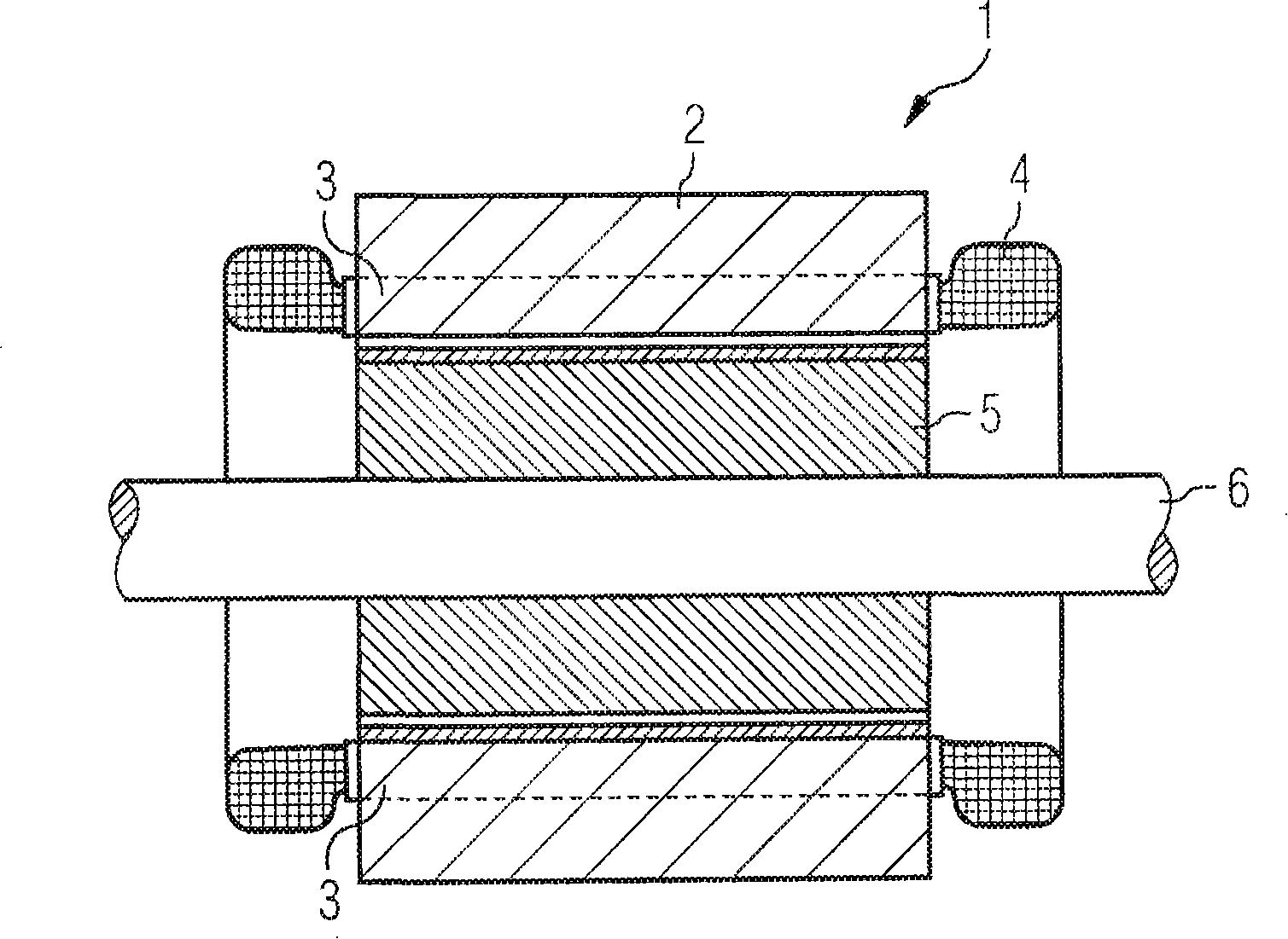
[0042] figure 1Shown is a longitudinal section of a prior art electric machine 1 taken along its axis of rotation. The motor 1 has a stator 2 and a rotor 5 mounted around a rotating shaft. The stator 2 has a stator core 3 with a stator winding 4 for generating a rotating magnetic field. The stator winding 4 has a plurality of multi-phase (in particular three-phase) winding systems which are not shown in detail. The stator core 3 and the rotor core are usually implemented as laminations in order to achieve the purpose of reducing eddy current losses. Reference sign 6 denotes a rotor shaft which is a part of rotor 5 .

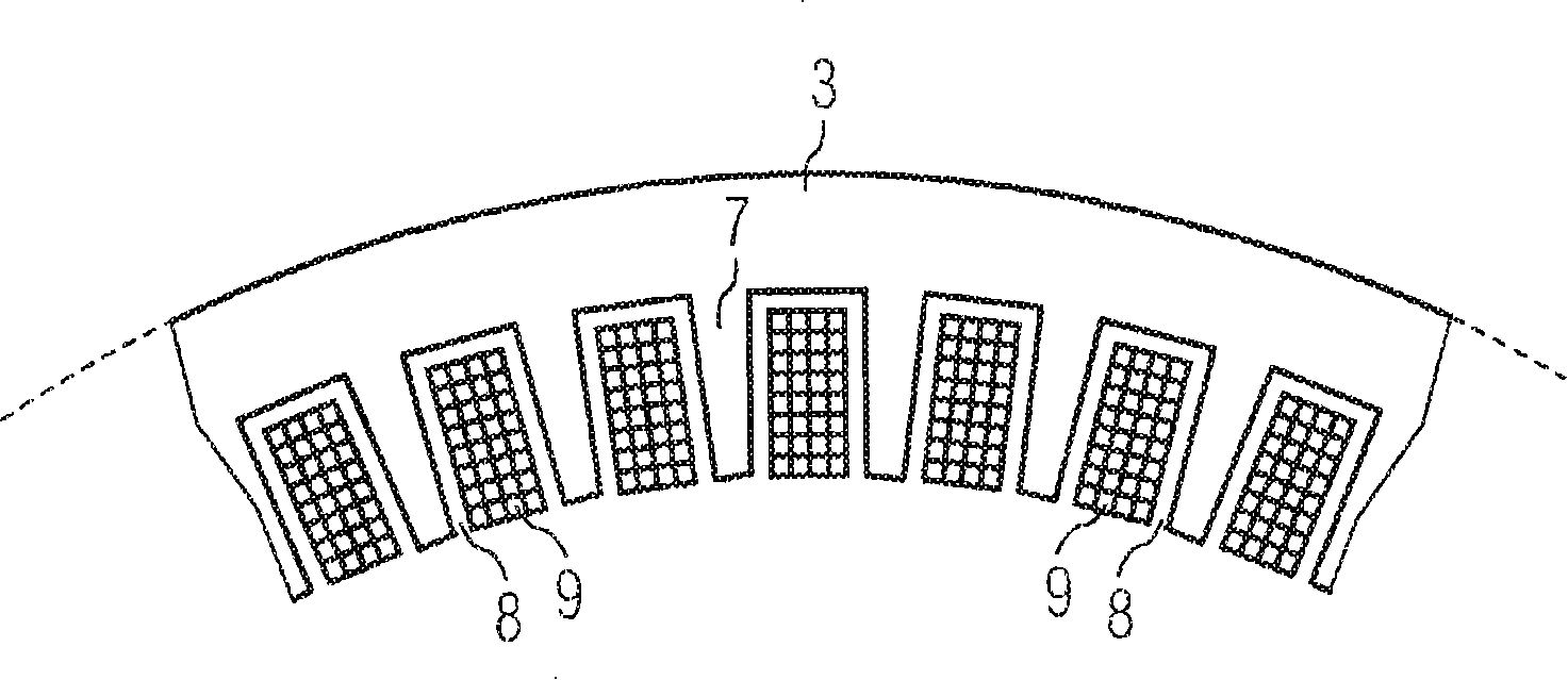
[0043] figure 2 Shown is a partial view of the laminations of the stator core 3 of the motor of the present invention. The electrical machine may be an electric motor or a generator. The motor can be a synchronous motor or an asynchronous motor. The electric machine is in particular a large electric machine with a rated power of at least 10 kW, especially...


PUM


Abstract

The electrical machine (1) has a stator (2) and a rotor (5), wherein the stator (2) has stator slots (8), in which a stator winding (4) with redundant and at least three-phase winding systems (U1, V1, W1; U2, V2, W2) is laid. According to the invention, the electrical machine (1) has a large number of poles with a pole number (PZ) of at least four, a number (NZ) of stator slots (8) which corresponds to the product of a phase number and the square of the pole number (PZ) of the electrical machine (1) or an integral multiple thereof, and a number of winding systems (U1, V1, W1;...; U4, V4, W4) which corresponds to the pole number (PZ). In each case a number of in-phase winding sections (U1-U4, V1-V4, W1-W4) which corresponds to the pole number (PZ) are combined to form a group of phase winding sections (PU, PV, PW). The phase winding section groups (PU, PV, PW) are laid, phase-cyclically and pole-for-pole, in the stator slots (8) of the stator (2). Depending on the pole and phase winding section group (PU, PV, PW), in each case are slot region (N1-N4) which corresponds to the pole number (PZ) is provided. The slot assignment takes place in such a way that the in-phase winding sections (U1-U4, V1-V4, W1-W4) are distributed, corresponding to their numbering, uniformly amongst the slot positions (N1,..., N4) of the associated slot regions (N1-N4).

Description

technical field [0001] The invention relates to an electrical machine with a stator and a rotor, wherein the stator has a plurality of stator slots in which a stator winding is arranged, the stator winding being formed by a redundant winding system of at least three phases. Furthermore, the invention also relates to an electric drive having a motor of the type described above and a plurality of converters whose number corresponds to the number of poles of the motor, the converters being used to provide at least three-phase redundant winding systems of the motor powered by. Background technique [0002] Motors of this type, in particular electric motors like asynchronous or synchronous motors, are used for various drive tasks, for example for driving compressors. Synchronous motors are suitable for driving compressors operating at high speeds. The synchronous electric motor is preferably embodied as a two-pole lamination or as a solid-pole rotor or as a turbine rotor. [0...

Claims


Application Information

Patent Timeline
Patent Type & Authority Patents(China)
IPC IPC(8): H02K3/16H02K3/28
CPCH02K2201/15H02K16/04H02P25/22H02K3/28
Inventor 玛丽亚·巴德阿克塞尔·莫尔
Owner SIEMENS AG
Why Eureka
Try Eureka