Electronic tube inverting amplifying circuit

An inverting amplification and electron tube technology, which is applied in the direction of electron tube amplifiers, amplifiers with semiconductor devices/discharge tubes, amplifiers, etc., can solve problems such as output signal phase imbalance, achieve consistent equivalent capacitance, and comprehensive sound performance , the effect of improving the sense of hearing

Inactive Publication Date: 2004-09-01
刘众轶
View PDF0 Cites 0 Cited by
  • Summary
  • Abstract
  • Description
  • Claims
  • Application Information

AI Technical Summary

Problems solved by technology

[0019] The object of the present invention is to provide an electron tube inverting amplifying circuit which not only solves the disadvantage of the phase imbalance of the output signal of the traditional inverting amplifying circuit but also maintains its advantages

Method used


Image

  • Electronic tube inverting amplifying circuit
  • Electronic tube inverting amplifying circuit
  • Electronic tube inverting amplifying circuit

Examples


Embodiment Construction

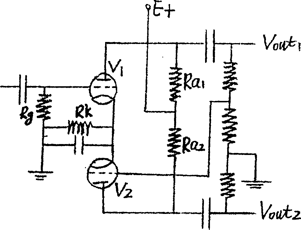
[0030] The present invention adopts direct-coupled voltage-dividing circuit structure, such as Figure 4 As shown, two tubes V1 and V2 of the same type jointly complete the task of inverting and amplifying; Ra1 and Ra2 are the load resistances of tubes V1 and V2 respectively, one end is connected to the positive end of the same group of power supplies, and the other end is respectively connected to V1, The screen electrode of the V2 tube; Rk1 and Rk2 are the negative bias resistors of the V1 and V2 tubes respectively, one end is respectively connected to the cathode of the V1 tube (point B) and the cathode of the V2 tube (point C), and the other end is grounded; R1 and R2 are connected in series , forming a voltage divider circuit, the upper end is connected to the screen electrode of the V1 tube, the lower end is grounded, and the middle end (point A) is directly coupled to the input grid of the V2 tube; Rg is the grid leakage resistance of the V1 tube, and one end is connecte...


PUM


Abstract

The present invention has opened an eletron tube phase reverse amplification circuit used for electron tube push-pull power amplification circuit to the public which includes two amplificatino units and direct-coupled differential pressure connection being applied in between two units. The present invention utilizes the strong point of traditional phase reverse circuit and overcomes the shortcomings of phase unbalanced in output signal of traditional phase reversal amplification circuit so that it has the advantages of circuit in simple structure, high efficiency of amplification and stable performance for to be used widely in power amplificatino of high fidelity sound appliance, radio emission and all kinds of electron tube fields required high efficiency and high accuracy.

Description

field of invention [0001] The invention relates to an electronic tube inverting amplifying circuit, in particular to an electronic tube inverting amplifying circuit applied to high-fidelity audio power amplification and some radio transmissions requiring high efficiency and high precision. Background technique [0002] The electronic tube is the oldest electronic amplifier device. In the late 1950s, due to the appearance of the transistor, the electronic tube was almost eliminated, but today, it is not possible to completely withdraw it from the electronic field. First of all, in the audio industry, people In the long-term use of transistor power amplifiers, it is generally found that transistor power amplifiers are difficult to replace tube power amplifiers in terms of sound quality and timbre, especially in terms of the artistry of sound performance, and there are some factors that affect sound quality that are difficult to overcome. In the popularization...

Claims


Application Information

Patent Timeline
IPC IPC(8): H03F3/00H03F3/02H03F3/181
Inventor 刘众轶
Owner 刘众轶
Why Eureka
Try Eureka