
Omnidirection monitoring system and monitoring method without blind spot

A monitoring system, technology without blind spots, applied in the direction of closed-circuit television systems, etc., can solve the problems of monitoring blind spots, incomplete monitoring information, camera damage, etc., and achieve the effect of ensuring reliable realization

Inactive Publication Date: 2009-01-28
ZTE CORP
View PDF0 Cites 25 Cited by
  • Summary
  • Abstract
  • Description
  • Claims
  • Application Information

AI Technical Summary

Problems solved by technology

[0003] However, there are some problems in the current model: 1. There is no differential treatment according to the different monitoring places; for places that are not very important, it may be possible to use a camera for monitoring, such as schools or general companies, but for important places such as banks, it must be It is necessary to ensure all-round non-blind-spot monitoring, and to have a certain degree of robustness. When some monitoring equipment is not working properly, it can still maintain all-round non-blind-spot monitoring; obviously for different places, it should be treated differently.
2. The environment where the camera is installed is diverse. In some environments, the camera is easily damaged by nature or man-made. Obviously, for such an environment, if the camera does not work normally, it will cause monitoring blind spots and monitor information. Incomplete, it is possible to miss important monitoring information

Method used


Image

  • Omnidirection monitoring system and monitoring method without blind spot
  • Omnidirection monitoring system and monitoring method without blind spot

Examples


Embodiment Construction

[0022] The present invention will be described in further detail below through specific embodiments and in conjunction with the accompanying drawings.

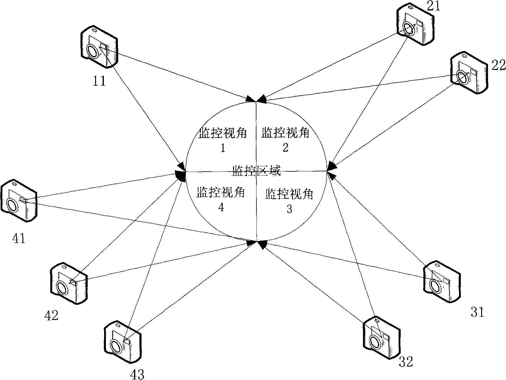
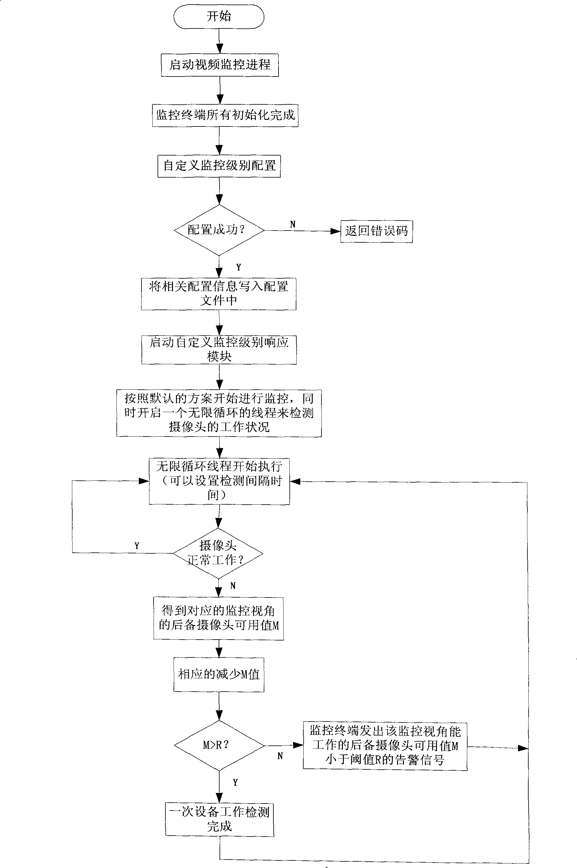
[0023] The all-round non-blind-spot monitoring system in this example includes a video monitoring center and 8 cameras. The video monitoring center adds a custom monitoring level configuration module, which can configure corresponding monitoring levels for different monitoring angles or positions, and different monitoring The level sets the corresponding monitoring threshold R; the video monitoring center adds a custom monitoring level response module, which is a background thread and always monitors whether the camera is working normally. This module can work according to the user's configuration parameters. respond differently to the situation.

[0024] Such as figure 1 As shown, in this example, the entire monitoring area is divided into four monitoring areas, and 8 cameras are used to monitor them. One camera 11 is config...


PUM


Abstract

The present invention discloses a monitoring system and a method for realizing omnibearing blindspotless monitoring. The system comprises a video monitoring center and a plurality of cameras connected thereto. A custom monitoring level configuration module and a custom monitoring level response module are arranged on the video monitoring center. The custom monitoring level configuration module sets the monitoring level for different angles or positions. The number of the cameras for monitoring different angles or positions is configured according to the monitoring level. The custom monitoring level responses to the working state of the real-time monitoring camera and carries out a real-time response according to the real-time monitoring result. The method adopts the redundancy mechanism and adopts a plurality of cameras to monitor one angle of a monitored area. When some cameras do not work normally, the monitoring center can monitor the result in real time and carry out response, and enables a backup camera, automatically or through the intervention of a user, and thus the realization of the omnibearing blindspotless monitoring can be ensured and the integrity and the reliability of the monitoring information can be ensured.

Description

【Technical field】 [0001] The invention relates to a monitoring system. 【Background technique】 [0002] With the development of computer and network technology, digital video surveillance system has gradually become an important application in the fields of finance, transportation, commerce, electric power, public security, customs, national defense and even residential areas. This kind of application is generally carried out by installing cameras in some important places. The user controls the pan / tilt according to the needs, and adjusts the camera lens to a suitable angle to monitor the target in real time. Most of the current monitoring systems are in this mode. [0003] However, there are some problems in the current model: 1. There is no differentiated treatment according to the different monitoring places; for places that are not very important, it may be possible to use a camera for monitoring, such as schools or general companies, but for important places such as bank...

Claims


Application Information

Patent Timeline
IPC IPC(8): H04N7/18
Inventor 马晓飞
Owner ZTE CORP
Learn More