
Off-the-road tyre tread pattern

A tire tread and construction machinery technology, applied in the field of tire tread patterns, can solve the problems of non-wear resistance, easy sand and stones, and resistance to cutting, so as to improve wear resistance and puncture resistance, and prevent flower collapse block, avoiding early damage effects

Inactive Publication Date: 2009-01-28
HAOHUA SOUTH CHINAGUILIN RUBBER
View PDF0 Cites 1 Cited by
  • Summary
  • Abstract
  • Description
  • Claims
  • Application Information

AI Technical Summary

Problems solved by technology

It can be seen that the design of the tire tread pattern has a great influence on the use of the tire, that is, the environment in which the tire is used. Driving under the conditions of driving, and there are a lot of sand, gravel and silt on the driving road, so it is necessary to have a tread pattern with strong self-cleaning ability, ideal wear resistance and puncture resistance, and will not cause stress concentration and lead to chipping and chipping. However, the tread pattern of existing construction machinery bias tires is generally easy to trap sand and stones, easy to collapse, not resistant to cutting, not resistant to puncture and not wear-resistant, which not only causes early damage to the tire, but also affects To the maneuverability of engineering vehicles, it cannot meet the requirements of the above-mentioned engineering vehicles

Method used


Image

  • Off-the-road tyre tread pattern
  • Off-the-road tyre tread pattern
  • Off-the-road tyre tread pattern

Examples


Embodiment Construction

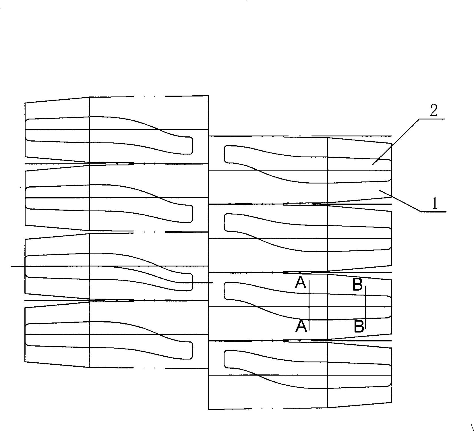
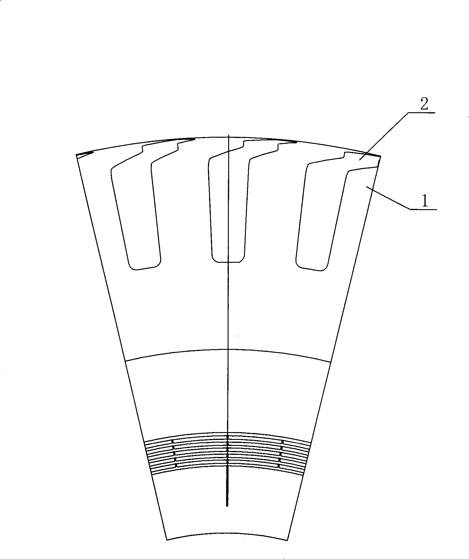
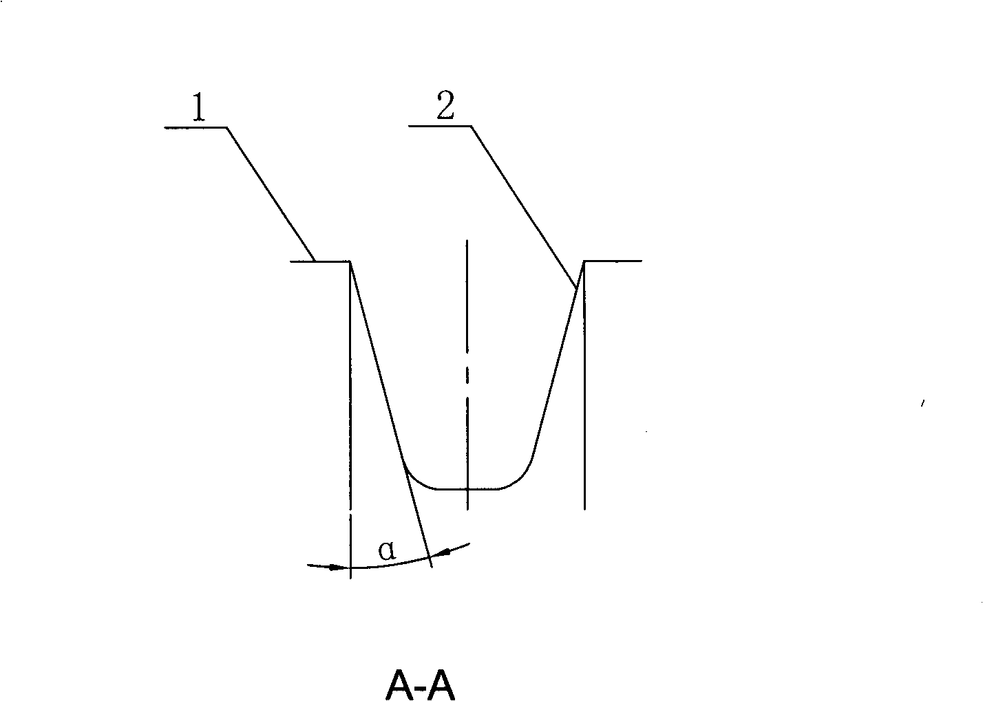
[0022] exist figure 1 In the illustrated embodiment, the present invention is a tread pattern of a bias tire used for a dump truck, including lateral grooves 2 and blocks that are offset in the circumferential direction and are reversely symmetrical with respect to the centerline of the tread 1. The transverse groove 2 starts from the center line of the tread at a position of 6-8% of the tread width to the tire shoulder and extends to the rib groove 2 on the sidewall. The upper and lower grooves of the groove 2 are evenly spaced It is "S" shape, the curvature of the upper groove edge is smaller than that of the lower groove edge; the upper groove edge at the groove head of the pattern groove 2 protrudes outward of the groove, and the upper groove edge of the rest of the crown is recessed toward the groove; The upper groove protruding outside the groove is recessed into the groove along the lower groove edge corresponding to the projected length, and the upper groove recessed i...


PUM


Abstract

The invention discloses tread patterns of construction machinery rubber tires and the patterns comprise transverse tread blocks and tread grooves; wherein, the transverse tread blocks and tread grooves dislocate in the circumferential direction and take a center line of the tread as the reference to be antisymmetric; the transverse tread grooves are stripy tread grooves which are arranged from the place close to the center line to a tire shoulder and extend to the tire side, and each tread block is repeatedly allocated into the form of equal interval, and upper groove edges and lower groove edges of the tread grooves are both of the shape of S and the curvature of the upper groove edges is smaller than that of the lower groove edges; the upper groove edges at groove heads of the tread grooves are convex outside a groove and the upper grooves edges of the rest part on a tire tip are concave inside the groove; the lower groove edges which are in the corresponding projection length of the upper groove edges which are convex outside the groove are concave inside the groove and the lower groove edges in the corresponding projection length of the upper groove edges which are concave inside the groove are convex outside the groove; the upper groove edges and lower groove edges of the tread grooves at the tire side are two straight lines which are approximately parallel. The tread patterns of construction machinery rubber tires are high in self-cleanness and good in wear resistance and piercing resisting performance and are particularly suitable for skew tires used in engineering vehicles such as dump trucks, bulldozers or wheel loaders.

Description

(1) Technical field: [0001] The invention relates to a tire tread pattern, in particular to an engineering machinery tire tread pattern. (two) background technology: [0002] Depending on the purpose of the tire and the environment in which it is used, the tire is required to have different performances. For example, for high-speed car tires, the heat dissipation and grip performance of the tire are high, but the requirements for other such as traction performance are not very high; Excellent handling stability, suitable for driving in wild road conditions and widely welcomed by off-road vehicle drivers, but its wet road skid performance is worse than other types of tires. The performance of the tire depends largely on the tread structure of the tire in direct contact with the ground. The tread structure of the tire is mainly the tread pattern, which is composed of grooves and blocks. It can be seen that the design of the tire tread pattern has a great influence on the use...

Claims


Application Information

Patent Timeline
Patent Type & Authority Applications(China)
IPC IPC(8): B60C11/13
Inventor 唐莹
Owner HAOHUA SOUTH CHINAGUILIN RUBBER
Learn More