
Electromagnetic compatible transmitting test method

A test method and electromagnetic compatibility technology, applied in the field of electromagnetic induction, can solve problems such as insufficient accuracy, lack of accuracy, and inability to recognize test results, and achieve the effects of saving time, increasing speed, and saving the time required for testing

Inactive Publication Date: 2009-01-21
BEIHANG UNIV
View PDF0 Cites 20 Cited by
  • Summary
  • Abstract
  • Description
  • Claims
  • Application Information

AI Technical Summary

Problems solved by technology

However, there is no theoretical support for the selection of benchmark comparison curves. It is impossible to achieve the purpose of shortening the test time after increasing the bandwidth by setting the benchmark curve based on experience during the test, let alone the recognition of the test results after increasing the bandwidth. The accuracy of the statement that this curve is beyond the standard is lacking
Although this saves test time, the accuracy of the test is not enough

Method used


Image

  • Electromagnetic compatible transmitting test method
  • Electromagnetic compatible transmitting test method
  • Electromagnetic compatible transmitting test method

Examples


Embodiment Construction

[0035] The present invention will be further described in detail below in conjunction with the accompanying drawings.

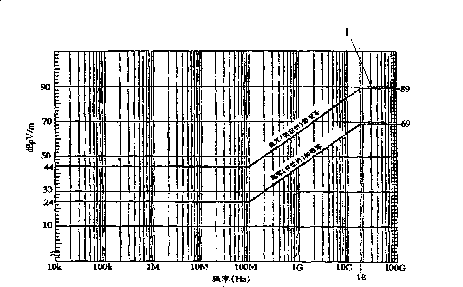
[0036] The following specific implementation methods are described by taking the national military standard RE102 as an example, and taking the (fixed) ground equipment applicable to the Air Force and Navy as an example. Such as figure 1 As shown, the specified limit value curve is required for this scope of application. The limit value curve 1 is 44dBμV / m at 10k-100MHz, and 89dBμV / m at 18G-100GHz. The limit is 89dBμV / m at 100MHz-18GHz. It is a monotonically increasing change from 44dBμV / m to 89dBμV / m.

[0037] Use the device and its parameters:

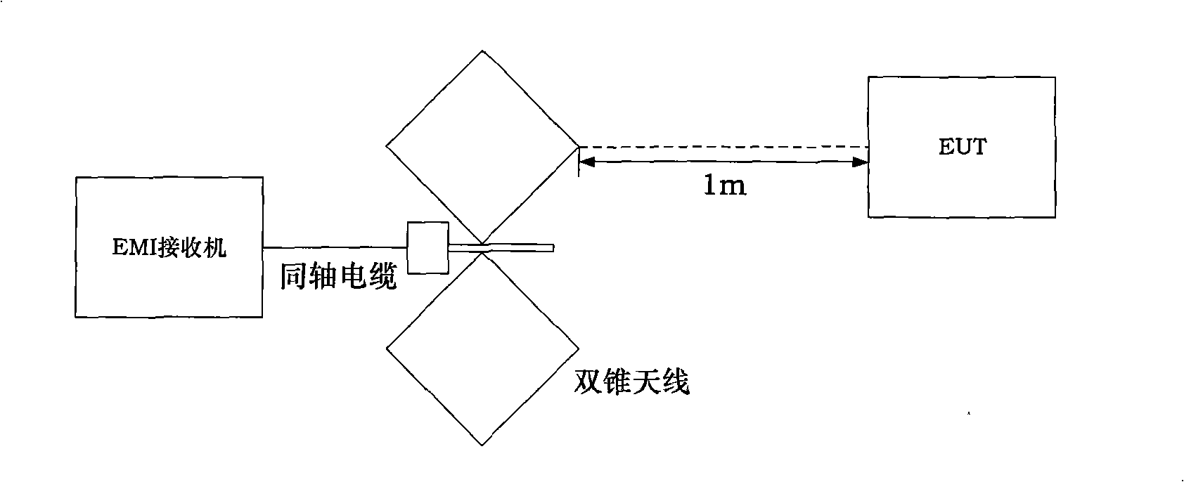
[0038] This method is mainly used in the electromagnetic interference test, taking RE102 as an example, such as figure 2 As shown, the biconical antenna receives the electric field strength emitted by the useless signal of the EUT (Equipment Under Test), and transmits the received signal to the EMI receiver thro...


PUM


Abstract

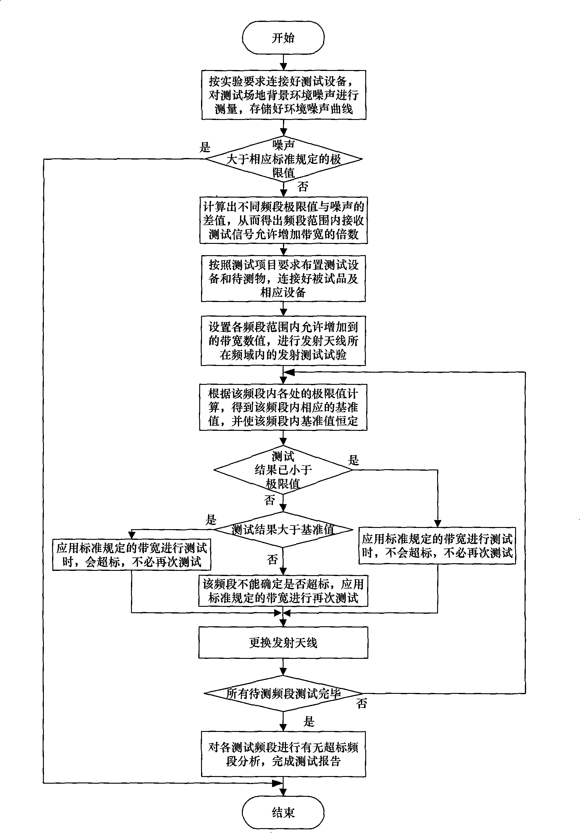
The invention provides an electromagnetic compatibility emission test method, which adopts standard measurement bandwidth to improve measurement bandwidth before an emission test to confirm that the invention can process prior measurement when the lowest noise of an EMI receiver is not higher than a standard limit value and the invention can compare the curve lines of the measurement result and the limit value to find a corresponding electromagnetic compatibility problem. The invention adopts the standard measurement bandwidth for the frequency range exceeded the limit value, to improve the test sped of the whole electromagnetic compatibility, save test time, and accurately and quantitatively determine the test result for the emission test on a sample.

Description

technical field [0001] The invention relates to the field of electromagnetic induction, in particular to an electromagnetic compatibility emission testing method. Background technique [0002] Electromagnetic compatibility (EMC) is a science that studies the coexistence of various electrical equipment or systems under the conditions of limited space, limited time, and limited spectrum resources without causing performance degradation. The purpose of electromagnetic compatibility research is to neither interfere with adjacent equipment and the environment, nor reduce indicators due to interference from adjacent equipment or environmental influences. With the rapid development of electronic technology, the application of equipment such as integration and miniaturization, especially in complex environments, where multi-purpose and multi-functional equipment and instruments coexist, the requirements for normal work are becoming more and more intense. Therefore, the requirements ...

Claims


Application Information

Patent Timeline
Patent Type & Authority Applications(China)
IPC IPC(8): G01R31/00
Inventor 戴飞谢树果曹景阳苏东林李益民邵康
Owner BEIHANG UNIV
Learn More