
Double-circulating fluid bed system for chemical chain combustion

A technology of chemical chain combustion and fluidized bed, which is applied to the fuel, fluidized bed combustion equipment, combustion method and other directions of melting state combustion, which can solve the problems of poor controllability and stability, reducing system efficiency and increasing system energy consumption. , to achieve the effect of improving stability, reducing system energy consumption, and improving operating efficiency

Inactive Publication Date: 2009-01-21
XI AN JIAOTONG UNIV
View PDF0 Cites 11 Cited by
  • Summary
  • Abstract
  • Description
  • Claims
  • Application Information

AI Technical Summary

Problems solved by technology

However, this dual fluidized bed system also has the disadvantage of complex operation, especially the system has two flow sealing valves, so that they can stably transport materials and prevent gas leakage, the height of their respective standpipes must be considered , Ventilation volume and wind pressure must be debugged several times to determine the appropriate air volume and wind pressure in order to ensure its normal operation, and it is also necessary to satisfy that the solids delivered by the two flow sealing valves must be approximately equal, and this sealing valve is right The adjustment effect of solid particle flow is very small. If the flow rate is large, its controllability and stability will be poor. These factors increase the complexity and instability of the system.
In addition, during the operation of the two flow-sealed valves, fluidizing gas needs to be introduced to fluidize the oxygen-carrying agent, which increases the energy consumption of the system and reduces the efficiency of the system

Method used


Image

  • Double-circulating fluid bed system for chemical chain combustion

Examples


Embodiment Construction

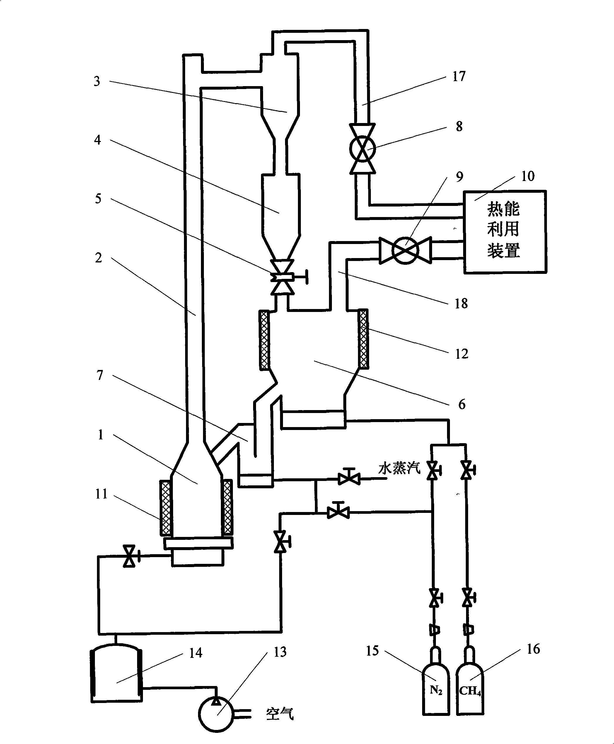
[0011] refer to figure 1 , in the present invention, fast fluidized bed 1, riser 2, cyclone separator 3, oxygen-carrying agent reservoir 4, solid flow control valve 5, bubbling bed 6, flow sealing valve 7 are connected successively, constitute the oxygen-carrying agent circulatory system. In the system, the positions and heights of the cyclone separator 3, the oxygen-carrying agent storage 4, the solid flow control valve 5, the bubbling bed 6, the flow sealing valve 7, and the fast fluidized bed 1 decrease successively.

[0012] The cyclone separator 3 is connected with the thermal energy utilization device 10 through the first exhaust pipe 17, and the first back pressure valve 8 is arranged on the first exhaust pipe 17; the bubbling bed is connected with the thermal energy utilization device 10 through the second exhaust pipe 18 , the second exhaust pipe 18 is provided with a second back pressure valve 9 .

[0013] A first heater 11 is arranged on the periphery of the fast ...


PUM


Abstract

The invention relates to the clean-burning and efficient utilization field of fuels, in particular to a double-circulating fluidized bed system used for chemical-looping combustion. The double-circulating fluidized bed system comprises a heat energy utilization device, a bubbling bed, a loop seal, a fast fluidized bed, a lift pipe and a cyclone separating device, wherein the bubbling bed, the loop seal, the fast fluidized bed, the lift pipe and the cyclone separating device are sequentially connected, the cyclone separating device is communicated with the heat energy utilization device through a first exhaust pipe, and the bubbling bed is communicated with the heat energy utilization device through a second exhaust pipe. The double-circulating fluidized bed system is characterized in that an oxygen carrier reservoir and a solid flow control valve are arranged between the outlet of the cyclone separating device and the inlet of the bubble column.

Description

technical field [0001] The invention relates to the field of clean combustion and high-efficiency utilization of fuel, in particular to a double-circulation fluidized bed system for chemical chain combustion. Background technique [0002] Chemical-Looping Combustion (CLC for short), its basic principle is to decompose the combustion of traditional fuel in direct contact with air into two gas-solid The reaction, on the one hand, uses the oxygen carrier to separate the oxygen in the air, and on the other hand, the oxygen carrier transfers the oxygen in the air to the fuel to burn the fuel. Since there is no direct contact between fuel and air during the combustion process, the combustion products are only carbon dioxide and water vapor, and carbon dioxide can be separated by simple cooling methods. In addition to this advantage, chemical looping combustion technology can also improve energy utilization. [0003] For the utilization system of chemical looping combustion techno...

Claims


Application Information

Patent Timeline
IPC IPC(8): F23C10/02
CPCY02E20/34
Inventor 王树众卢玲玲姜峰裴炜胡昕
Owner XI AN JIAOTONG UNIV
Learn More