
Hammer leaf type drum sieve pulverizing machine

A trommel screen and pulverizer technology, applied in the direction of filter screen, solid separation, grid, etc., can solve the problems of low pulverization efficiency, poor micro pulverization effect, motor power loss, etc., to improve the screening ability, improve pulverization efficiency, Guaranteed quality effect

Inactive Publication Date: 2010-04-21
王庆辉
View PDF6 Cites 1 Cited by
  • Summary
  • Abstract
  • Description
  • Claims
  • Application Information

AI Technical Summary

Problems solved by technology

[0002] At present, the hammer mill with sieve is one of the most widely used crushing models in production. The chips are fixed or vibrated within a certain range. Their disadvantage is that they are only suitable for coarse crushing, and the effect is poor for fine crushing. Due to the action of centrifugal force, the material is separated from the impact of the hammer, and soon forms a material ring inside the screen. The quality of the coarse and fine materials is different, resulting in the layering of the material ring, and the coarse particle layer is close to the screen. On the side of the sheet, the fine grain layer covers the coarse grain layer to form a circulation layer
In the case that the circulation layer of the material cannot be destroyed, it will not only affect the return of the coarse particle material to the crushing area, but also affect the screening of qualified particles.
Especially in the process of micro-grinding, the hammer-sieve gap and sieve holes are small, and the rotor speed is high, so it is difficult for the material to pass through the sieve plate, which increases the friction and heat generation between the material and the sieve plate, which makes the temperature of the material rise, and the noise is large. At the same time, it also causes excessive crushing of materials in the crushing chamber, and the crushing capacity of the crushing machine is insufficient, so there is inevitably a serious blockage of the circulating layer, which makes the crushing efficiency low.

Method used


Image

  • Hammer leaf type drum sieve pulverizing machine
  • Hammer leaf type drum sieve pulverizing machine
  • Hammer leaf type drum sieve pulverizing machine

Examples


Embodiment Construction

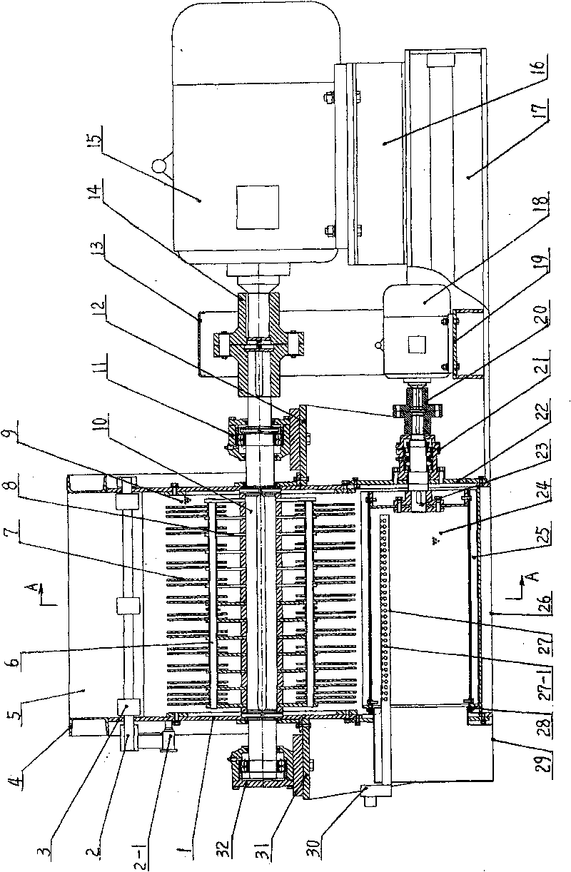
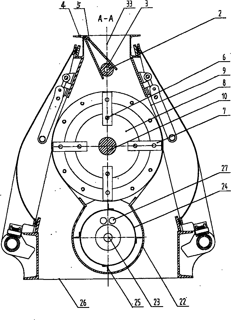
[0011] Examples, see attached figure 1 , 2 , a main motor seat 16 is fixed on the right end surface of the base 17 of the hammer-type trommel mill and its crushing method, the main motor seat 15 is fixed above the main motor seat 16, and the main motor 15 shaft is connected to the pulverizer main shaft 10 with a coupler-14, Dress cover 13 above shaft coupling one 14. Bearing block 3 32 and bearing block 11 at the left and right ends of the pulverizer main shaft 10 are fixed on the bearing block 3 support 31 and bearing seat 1 support 12, and the rotor 8 is fixed on the circumferential surface of the pulverizer main shaft 10, and the blades of the rotor 8 Several hammer shafts 6 are fixed in the middle, and several hammers 7 are fixed on the hammer shafts 6; a pulverizer sieve 9 is fixed on the outer pulverizer shell of the hammer 7, and the pulverizer rotor 8 is installed on the lower end belt. In the open drop-shaped casing 1. The upper end of the pulverizer shell 1 is fix...


PUM


Abstract

The invention belongs to crushing machinery, which more particularly relates to a hammer drum sieve crushing machine and a crushing method thereof which are applicable to food, feed, chemical and other fields, the crushing machine consists of a base (17), an upper rack (4), a main motor (15), a coupling (14), a shell body (1) of the crushing machine, a main shaft (10) of the crushing machine, a rotor (8), a hammer (7) and a material guide plate (5), and the crushing method is as follows: raw materials enter the crushing machine, qualified small particles penetrate a fixed sieve plate of the crushing machine under the high-speed hit of the hammer on the rotor, the qualified small particles which are not timely discharged and the unqualified large particles are thrown to the sieve surface ofa rotating drum sieve by the rotor at a certain speed, thereby leading the working sieve surface to always maintain the high efficient sieving ability which is equivalent to increasing several timesofthe effective sieving area, improving the sieving ability of the original sieve plate of the crushing machine, improving the crushing efficiency and ensuring the quality of crushed materials.

Description

technical field [0001] The invention belongs to a crushing machine, in particular to a hammer-type trommel grinder and a crushing method suitable for the fields of grain, feed, chemical industry and the like. Background technique [0002] At present, the hammer mill with sieve is one of the most widely used crushing models in production. The chips are fixed or vibrated within a certain range. Their disadvantage is that they are only suitable for coarse crushing, and the effect is poor for fine crushing. Due to the action of centrifugal force, the material is separated from the impact of the hammer, and soon forms a material ring inside the screen. The quality of the coarse and fine materials is different, resulting in the layering of the material ring, and the coarse particle layer is close to the screen. On the sheet side, the fine grain layer is covered on the coarse grain layer to form a circulation layer. In the case that the circulation layer of the material cannot be...

Claims


Application Information

Patent Timeline
Patent Type & Authority Patents(China)
IPC IPC(8): B02C13/13B02C13/284B07B1/22B07B1/55
Inventor 王庆辉
Owner 王庆辉
Learn More