Subscriber premise optical line terminating apparatus and optical transmission system

An optical line terminal and optical transmission technology, applied in the field of optical transmission systems, can solve problems such as increasing equipment installation space and reducing reliability.

Active Publication Date: 2009-01-14
FURUKAWA ELECTRIC CO LTD
View PDF1 Cites 6 Cited by
  • Summary
  • Abstract
  • Description
  • Claims
  • Application Information

AI Technical Summary

Problems solved by technology

[0010] Therefore, when connecting multiple terminal equipment to the terminal of the optical transmission line, there is a need to connect the ONU to its terminal, and then use a cable to connect the ONU and the router or switch Trouble connecting between hubs
In addition, for these devices and their ONU power supply arrangement and cable lead-back, it is necessary to ensure a large equipment installation space. On the other hand, there is also a problem that the overall reliability of the structural equipment is reduced due to the ONU power supply and cables.

Method used


Image

  • Subscriber premise optical line terminating apparatus and optical transmission system
  • Subscriber premise optical line terminating apparatus and optical transmission system
  • Subscriber premise optical line terminating apparatus and optical transmission system

Examples


Embodiment Construction

[0062] Embodiments of the present invention will be described in detail below with reference to the accompanying drawings.

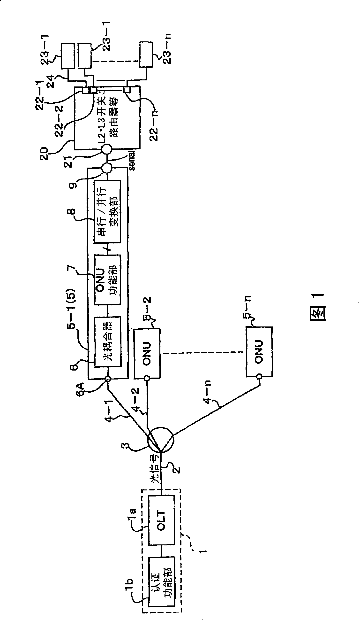
[0063] FIG. 1 is a configuration diagram of a PON-type optical transmission system according to an embodiment of the present invention.

[0064] In the PON system shown in Figure 1, the PON interface card 1 arranged at the center has an optical line terminal unit (OLT) 1a and an authentication function part 1b, and the optical input and output ends of the OLT1a are connected with one end of the optical fiber 2 as the optical transmission path . In addition, the other end of the optical fiber 2 , that is, the user's house side, is connected to an optical coupler (optical multiplexer / demultiplexer) 3 .

[0065] Be branched into a plurality of optical transmission paths by the optical coupler 3, through optical fibers 4-1, ..., 4-n and a plurality of optical terminal units (ONU) 5-1, ..., 5-n of the user's house side (n : natural number) connection.

[0...


PUM


Abstract

The present invention provides a subscriber premise optical line terminating apparatus, which comprises an electricity / light converting means (6) that is connected to a center-side optical transmission path (2) to perform a light-to-electricity conversion and an electricity-to-light conversion; an optical line terminating apparatus function part (7) that is connected to an electric signal input / output terminal of the electricity / light converting means (6); a serial / parallel converting means (8) that is connected to parallel signal terminals of the optical line terminating apparatus function part (7) to perform a serial-to-parallel conversion or a parallel-to-serial conversion; and a multi-source agreement interface (9) that is connected to a serial signal terminal of the serial / parallel converting means (8).

Description

technical field [0001] The present invention relates to an optical line terminal device and an optical transmission system on the user's house side, and more specifically relates to an optical line terminal device equipped with a multi-source protocol interface module or a separate interface module installed at a terminal on the user's house side of an optical transmission line, and the device equipped with the same optical transmission system. Background technique [0002] In optical networks such as FTTH and CATV, as described in the following patent document 1, the optical transmission line connected to the center is branched by a passive splitter, and the PON (Passive Optical Network) type is laid to multiple user houses. The optical transmission system is being used. [0003] Such an optical transmission system is also called PDS (Passive Double Star). [0004] Such as Figure 8 As shown, in such an optical transmission system, an optical fiber 102 drawn from a centra...

Claims


Application Information

Patent Timeline
Patent Type & Authority Applications(China)
IPC IPC(8): H04L12/44H04B10/20H04B10/272
CPCH04B10/272H04J3/1694
Inventor 下大迫和隆尾高邦雄网干胜也
Owner FURUKAWA ELECTRIC CO LTD
Why Eureka
Try Eureka