
Disc clamping rotary plate

A turntable and disc technology, which is applied in the field of clamping turntables, can solve the problems of increased incidental costs of production costs, complex assembly projects, and increased project defect rates, and achieve the effects of simple manufacturing processes and reduced manufacturing costs and additional costs

Inactive Publication Date: 2009-01-07
WORLD TECH
View PDF1 Cites 1 Cited by
  • Summary
  • Abstract
  • Description
  • Claims
  • Application Information

AI Technical Summary

Problems solved by technology

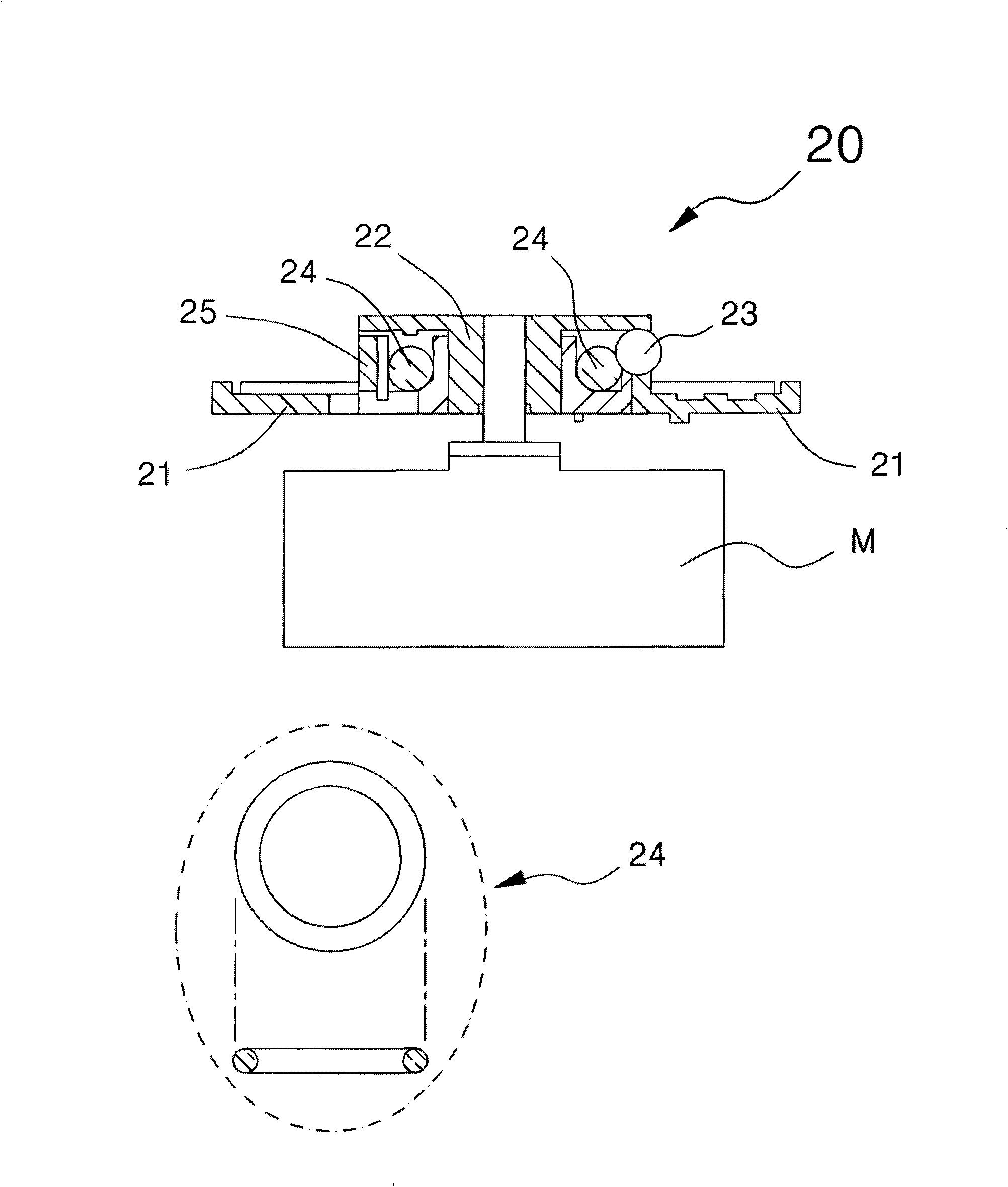
[0012] However, the above-mentioned turntable 20 is basically composed of steel balls, O-rings, and T-bushs, so there are problems in that the assembly process is complicated, and the defect rate increases due to the complexity of the process. Assembling parts needs to be produced by independent engineering, which causes an increase in production costs and incidental costs

Method used


Image

  • Disc clamping rotary plate
  • Disc clamping rotary plate
  • Disc clamping rotary plate

Examples


Embodiment Construction

[0061] The features and advantages of the present invention will be made clear by the following detailed description based on the accompanying drawings.

[0062] Before the description, the terms or words used in this description and the scope of the claims are for the inventor to explain his invention in the best way, starting from the principle of giving the most appropriate definition to the terms, and should be consistent with the technical idea of ​​the present invention meanings and concepts. In addition, please note that if it is judged that the detailed description of the known functions and configurations related to the present invention will affect the gist of the present invention, the detailed description will be omitted.

[0063] First of all, according to the preferred embodiment of the present invention, the disc clamping turntable 100 (hereinafter referred to as 'turntable') is as follows Figure 3a , Figure 3a' and Figure 3b As shown, it includes a circul...


PUM


Abstract

The invention relates to disk clamping rotary table, comprising a round disk and a central guiding part formed by an integral protruding of the central portion of the round disk. The central guiding part comprises three cut parts and clamping parts arranged at the extension with equal distance and elastic cut pieces extended respectively from the lower vertical part of the peripheral side and the cut part between the clamping parts; the center of the elastic cut pieces is cut; the clamping parts comprise a lower rainbow extended from the body of the central guiding part, a vertical rainbow extended vertically from the front end of the lower rainbow, and a bent part formed at the upper side of the vertical rainbow, and the bent part is partly protruding at the peripheral side; the elastic cut pieces comprise a first cut piece and a second cut piece with a part protruding toward the outer side of the lower vertical part. The disk clamping rotary table of the invention is not provided with a steel ball, an O-shaped ring or a T-bushing with the same functions and is formed integrally by injection, thus obviously simplifying the current manufacturing technique and obviously reducing manufacturing cost and additional expense.

Description

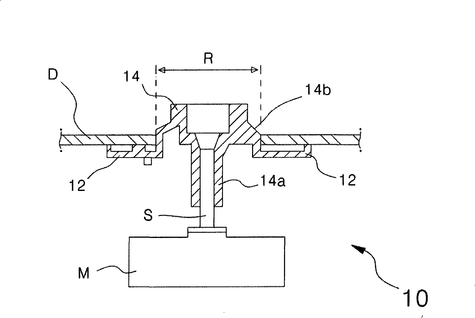
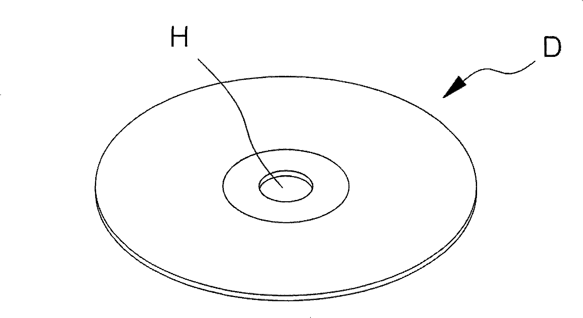
technical field [0001] The present invention relates to a disc clamping turntable, in particular to a turntable capable of stably chucking CDs or DVDs without additional assembly parts. Background technique [0002] The existing turntable structure is divided into two types according to whether there is a clamping device or not. [0003] First, attach Figure 1a It is a schematic diagram of a relatively low-precision turntable structure suitable for home CD players and CD-ROMs of desktop computers, etc., showing the support of the disc D (refer to Figure 1b ) bottom circular disk 12, and a turntable 10 formed integrally at the center of the circular disk 12 for inserting a cylindrical central guide member 14 into the center hole H for accommodating discs. [0004] In more detail, the lower part of the central guide member 14 has a central hole-shaped bobbin 14a integrally formed, and the rotating shaft S of the spindle motor M is inserted into the bobbin 14a. In addition,...

Claims


Application Information

Patent Timeline
IPC IPC(8): G11B17/022
Inventor 朴赞烈
Owner WORLD TECH
Learn More