Discrete optimizing method for magnetic resonance image-forming superconducting magnet design

A technology for magnetic resonance imaging and superconducting magnets, which is applied in the field of applied superconductivity and can solve the problems of difficult to achieve magnetic field index and robustness.

Inactive Publication Date: 2009-01-07
TSINGHUA UNIV
View PDF0 Cites 15 Cited by
  • Summary
  • Abstract
  • Description
  • Claims
  • Application Information

AI Technical Summary

Problems solved by technology

But the consequence of this is that it is difficult to achieve t

Method used


Image

  • Discrete optimizing method for magnetic resonance image-forming superconducting magnet design
  • Discrete optimizing method for magnetic resonance image-forming superconducting magnet design
  • Discrete optimizing method for magnetic resonance image-forming superconducting magnet design

Examples


Embodiment Construction

[0099] The principle and specific implementation of the present invention will be described below in conjunction with the accompanying drawings.

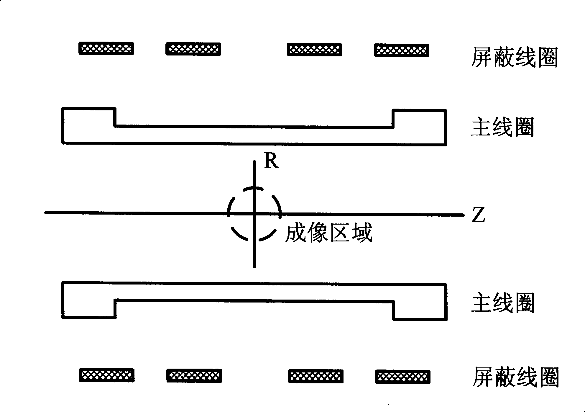
[0100] figure 1 It is the magnet structure selected in the embodiment of the present invention. The coils are symmetrical about the Z axis and about the Z=0 plane. The inner side of the magnet is the main coil, which adopts the form of an outer notch, and the outer side is two pairs of shielding coils. The shielding coil and the main coil are connected in reverse series. The radius of the inner hole of the magnet is 0.15m. Select the SuperCon C54S43 type superconducting wire, and set the current as I=240A.

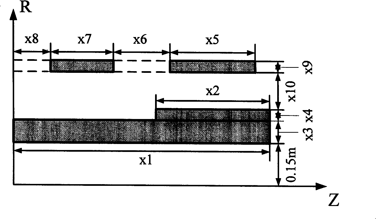
[0101] figure 2 is the optimization model variable setting diagram in the embodiment of the present invention. The diagram shows the first quadrant of the axial section. Variable X=[x1, x2, x3, x4, x5, x6, x7, x8, x9, x10], the meaning of each component of the variable is shown in the table below:

[0102] Table 1

[010...


PUM


Abstract

The invention relates to an optimization design method for the discretization of magnetic resonance imaging (MRI) superconducting magnets, which belongs to a superconducting magnet design technology and is characterized in that an objective function is set by a weighting method and indexes of magnetic field intensity, uniformity of magnetic field, stray field range, thread consumption, fabrication error, and the like are taken into comprehensive consideration. The use of discrete variables as optimization variables can avoid rounding and discretization errors occurring in common methods. By considering the robustness of errors in design objectives, the optimization design of the robustness is realized. The use of the design method for designing the superconducting magnets can take a plurality of design indexes into consideration in a synthesized manner, thus having the advantages of convenient processing and manufacturing and strong error robustness.

Description

technical field [0001] The invention belongs to the technical field of applied superconductivity, in particular to the design of a magnetic resonance imaging (MRI) superconducting magnet. Background technique [0002] Magnetic resonance imaging (MRI) is a technique that uses the phenomenon of nuclear magnetic resonance for imaging. The main magnet is an important part of the MRI system, and its function is to generate a background magnetic field with a specific strength and a certain degree of uniformity in the imaging area. Its electromagnetic design indicators are: [0003] (1) Magnetic field strength B 0 , refers to the magnetic field value at the center point of the imaging region (DSV). [0004] (2) Magnetic field uniformity, one definition method is [0005] H 0 = B dx - B di ...

Claims


Application Information

Patent Timeline
IPC IPC(8): G06F17/50
Inventor 郭伟蒋晓华梁嘉祺
Owner TSINGHUA UNIV
Why Eureka
Try Eureka