Electric charge sharing mode LCD device, source drive device and electric charge sharing method

A liquid crystal display and charge sharing technology, applied in static indicators, instruments, nonlinear optics, etc., can solve the problems of high cost, power consumption and large area of ​​the driver chip, and achieve the effect of reducing power consumption and simple control timing

Inactive Publication Date: 2011-05-18
BYD SEMICON CO LTD
View PDF0 Cites 0 Cited by
  • Summary
  • Abstract
  • Description
  • Claims
  • Application Information

AI Technical Summary

Problems solved by technology

[0002] With the development of TFT liquid crystal display in the direction of high integration, high resolution, multi-gray scale, etc., the power consumption and area of ​​the corresponding driver chip become larger and larger, and the cost becomes higher and higher.

Method used


Image

  • Electric charge sharing mode LCD device, source drive device and electric charge sharing method
  • Electric charge sharing mode LCD device, source drive device and electric charge sharing method
  • Electric charge sharing mode LCD device, source drive device and electric charge sharing method

Examples


Embodiment 1

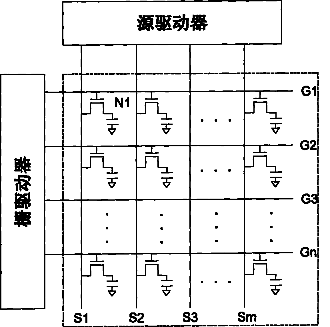
[0027] According to the liquid crystal display of the present invention, it includes a liquid crystal display, a grayscale generation circuit, a source driver, a gate driver and a logic control sequential circuit, and the structure of the liquid crystal display is as follows figure 1 As shown, a plurality of thin film transistors N1, a plurality of gate lines G1 and G2 insulated from each other and a plurality of data lines S1 and S2 are fabricated on the panel, and the gate, source and drain of each thin film transistor N1 are respectively connected to adjacent The gate line, data line and pixel electrode (not shown in the figure), the gate line is connected to the output terminal of the gate driver, and the data line is connected to the output terminal of the source driver. The gray scale generating circuit outputs the gray scale voltage to the source driver.

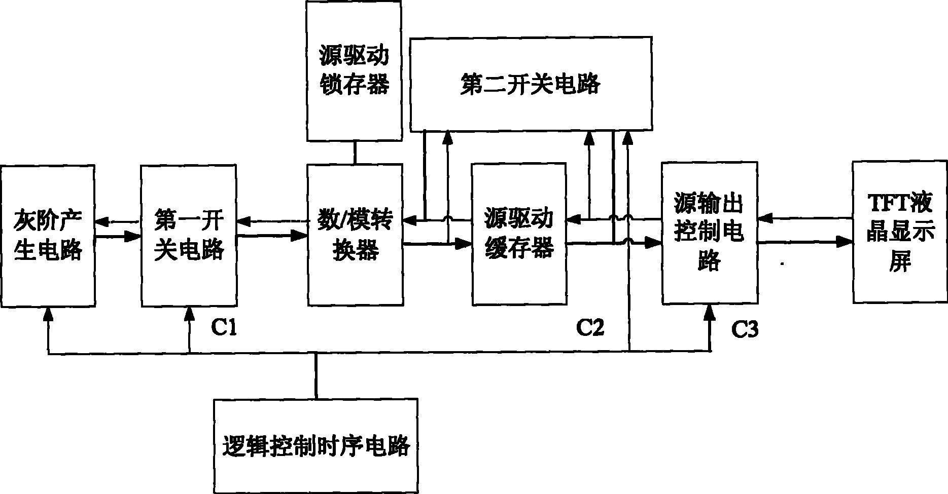
[0028] Such as figure 2 As shown, the source driver includes a sequentially connected source drive latch, a digit...

Embodiment 2

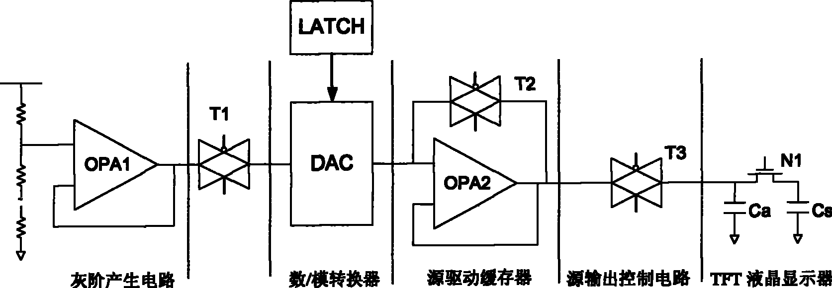
[0048] The difference between this embodiment and the first embodiment is that only the logic control sequence circuit is required to control the second switch circuit and the third switch circuit to have at least one coincidence that makes the second switch circuit and the third switch circuit conduct simultaneously. conduction period M, and the logic control sequence circuit controls the first switch circuit to be in an off state during at least one coincident conduction period, such as Figure 7 As shown, the first control sequence C1, the second control sequence C2 and the third control sequence C3 are periodic signals with the same cycle, the high level turns on the transistor, and there is a coincident conduction period M in each cycle , in the coincident conduction period M, the transmission gate T2 and the transmission gate T3 are simultaneously turned on, while the transmission gate T1 is turned off, and the conduction and disconnection of the thin film transistor have...


PUM


Abstract

The invention discloses a liquid crystal display having charge sharing mode, comprising a liquid crystal display screen, a grayscale generating circuit, a first switch circuit, a source driver, a gate driver and a logic control sequence circuit, the source driver comprising a source driving latch, a digital / analog converter, a source driving buffer and a source output control circuit which are sequentially connected, also comprising a second switch circuit, wherein the first switch circuit is serially connected between the grayscale generating circuit and the digital / analog converter, the second switch circuit is connected between the input terminal and the output terminal of the source driving buffer, the source output control circuit is a third switch circuit, and the logic control sequence circuit controls that the switch-on time of the second switch circuit and the third switch circuit at least has a coincident switch-on time arrange for synchronously switching on the second switch circuit and the third switch circuit, and controls the first switch circuit on a switch-off condition in at least a coincident switch-on time arrange. The liquid crystal display having charge sharing mode implements the charge sharing and reduces the power consumption of the source driver.

Description

【Technical field】 [0001] The present invention relates to a thin film transistor-liquid crystal display (TFT-LCD), in particular to a thin film that uses a charge sharing mode to reduce power consumption of a TFT-LCD driver (thin film transistor liquid crystal display driver chip / driver) without reducing the driving capability of the source driver Transistor liquid crystal display and its charge sharing method. 【Background technique】 [0002] With the development of TFT liquid crystal displays in the direction of high integration, high resolution, multi-gray scale, etc., the power consumption and area of ​​the corresponding driver chips are becoming larger and higher, and the cost is getting higher and higher. How to realize TFT-LCD driver source driver with smaller layout area and lower power consumption has become a problem that designers must consider. 【Content of invention】 [0003] The main purpose of the present invention is to solve the problems in the prior art, t...

Claims


Application Information

Patent Timeline
Patent Type & Authority Patents(China)
IPC IPC(8): G02F1/1362G09G3/36
CPCG09G3/3688G09G2330/021G09G2310/027
Inventor 龚夺何志强杨云冯卫
Owner BYD SEMICON CO LTD
Why Eureka
Try Eureka