
Bearing construction of motor

A bearing and structure technology, applied in the field of bearing structure, can solve the problems of increasing the frictional resistance between the oil bearing 8 and the shaft 9, easy loss of lubricating oil, shortening the service life of the motor, etc.

Inactive Publication Date: 2011-06-22
SUNONWEALTH ELECTRIC MACHINE IND
View PDF3 Cites 0 Cited by
  • Summary
  • Abstract
  • Description
  • Claims
  • Application Information

AI Technical Summary

Problems solved by technology

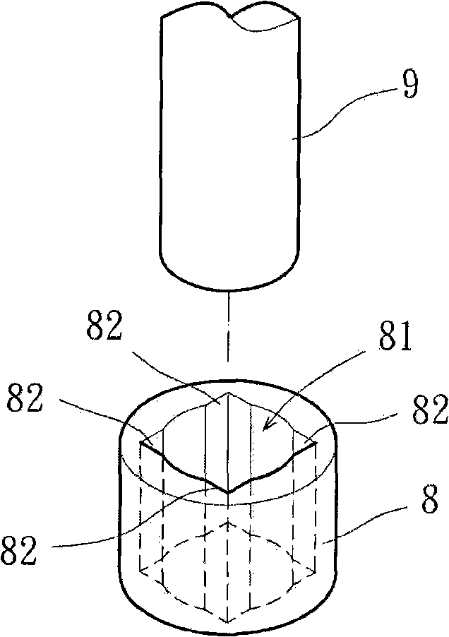
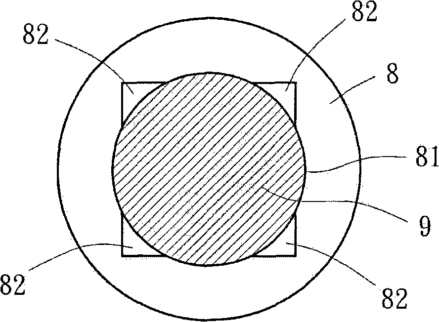
[0004] Generally speaking, the bearing structure of the above-mentioned existing motor has the following disadvantages, for example: when the shaft rod 9 is passed through the central hole 81 of the oil-impregnated bearing 8 and rotates, due to the bottom of the extension groove 82 and the oil-impregnated The bottom of the bearing 8 is connected, so the lubricating oil accumulated in the extension groove 82 is easy to lose, which affects the overall lubricating effect of the oil-impregnated bearing 8
In addition, external impurities (such as: dust or sand grains, etc.) are easy to fall into the gap between the oil bearing 8 and the shaft 9, and a lubricating oil space in the oil bearing 8 is also very easy to produce due to the rotation of the shaft 9. A carbide is formed at high temperature, and the carbide and impurities will increase the frictional resistance between the oil bearing 8 and the shaft 9, further shortening the service life of the motor

Method used


Image

  • Bearing construction of motor
  • Bearing construction of motor
  • Bearing construction of motor

Examples


Embodiment Construction

[0035] In order to make the above and other purposes, features and advantages of the present invention more obvious and understandable, the preferred embodiments of the present invention are specifically cited below, together with the accompanying drawings, as follows:

[0036] Please refer to image 3 , 4 As shown, the bearing structure 1 of the motor disclosed in the first embodiment of the present invention is preferably selected from an oil-impregnated bearing or a hydrodynamic bearing. The bearing 1 mentioned in the example is correspondingly assembled in a shaft tube 21 of the motor 2 and can be passed through by a rotor 22 of the motor 2 . A stator 23 is provided on the outer peripheral surface of the shaft tube 21 .

[0037] please refer again image 3 , 4 As shown, the bearing 1 described in the first embodiment of the present invention includes a shaft hole 10 and at least one guide groove 11, and the bearing 1 has two end faces, which are respectively a first end...


PUM


Abstract

The invention discloses a bearing structure of a motor. The bearing is correspondingly installed in an axle tube of the motor and comprises an axle hole and at least one guiding groove, wherein, the axle hole is arranged at the axis of the bearing to be supplied for being run through by a shaft lever of the motor; one end of the guiding groove runs through one end face of the bearing while the other end of the guiding groove does not run through the other end face of the bearing and a deposition space is formed at the bottom of the guiding groove. Therefore, carbide and impurities and the like produced by a lubricating fluid can deposit in the deposition space so as to further prevent the lubricating capacity of the lubricating fluid from being influenced by the carbide and impurities andalso extend the service life of the motor.

Description

technical field [0001] The invention relates to a bearing structure of a motor, in particular to a bearing structure in which at least one guide groove is arranged on the outer peripheral surface of a shaft hole of a bearing, and the guide groove penetrates an end surface of the bearing. Background technique [0002] The bearing structure of the existing motor, such as China Taiwan Announcement No. 542317 "oil-impregnated bearing" new patent, please refer to figure 1 , 2 As shown, the oil-impregnated bearing 8 includes a central hole 81 and several extension slots 82 , the central hole 81 is formed axially through the axial center of the oil-impregnated bearing 8 for a shaft 9 to pass through and fix. The extension groove 82 is correspondingly formed on the peripheral wall of the center hole 81 , and the extension groove 82 penetrates the top surface and the bottom surface of the oil-impregnated bearing 8 along the axial direction, thereby changing the cross-sectional shape...

Claims


Application Information

Patent Timeline
Patent Type & Authority Patents(China)
IPC IPC(8): H02K7/08F16C33/10F16C33/74
Inventor 洪银树
Owner SUNONWEALTH ELECTRIC MACHINE IND
Learn More