
Electrical quantity measuring device for electric cable

A measurement equipment and energy transmission technology, applied in measurement devices, measurement of electrical variables, measurement of current/voltage, etc., can solve problems such as low measurement accuracy, inability to accurately measure current intensity values, and difficulty in setting power lines.

Inactive Publication Date: 2008-12-24
С.ДЖ. Э. СОЧИЕТА ДЖЕНЕРАЛЕ ДИ ЭЛЕТТРОНИКА С.Р.Л.
View PDF4 Cites 16 Cited by
  • Summary
  • Abstract
  • Description
  • Claims
  • Application Information

AI Technical Summary

Problems solved by technology

[0015] The disadvantage of these current measuring devices is that they cannot measure current intensity values ​​with sufficient accuracy, especially on high and medium voltage power lines, because they are subject to disturbances due to the presence of electric fields generated by the power lines themselves
[0016] In fact this electric field creates a capacitive coupling and a source of interference which affects both the TA and the electronic circuits of the same device used to process the signals found in the vicinity of the power line, thus making the measurement accuracy of the said device very small on bare cables
[0017] Current and voltage measuring devices commonly used in the market find it difficult to set up in power lines in practice
[0018] Moreover, the different technical requirements of the two measuring devices make their assembly into a single measuring device almost impossible

Method used


Image

  • Electrical quantity measuring device for electric cable
  • Electrical quantity measuring device for electric cable
  • Electrical quantity measuring device for electric cable

Examples


Embodiment Construction

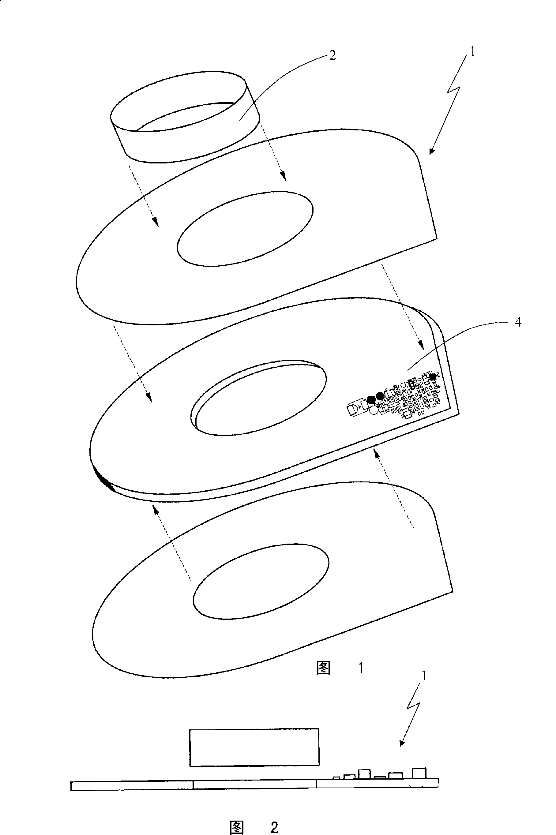
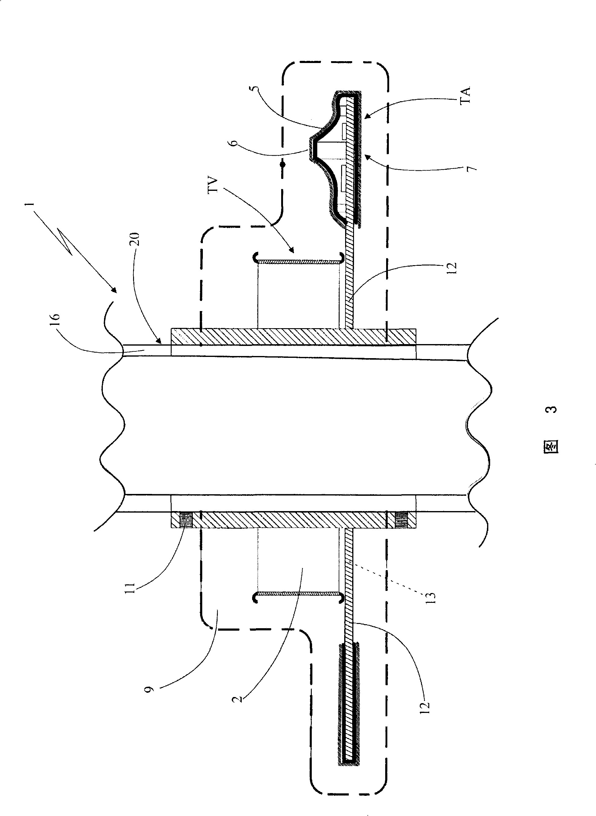
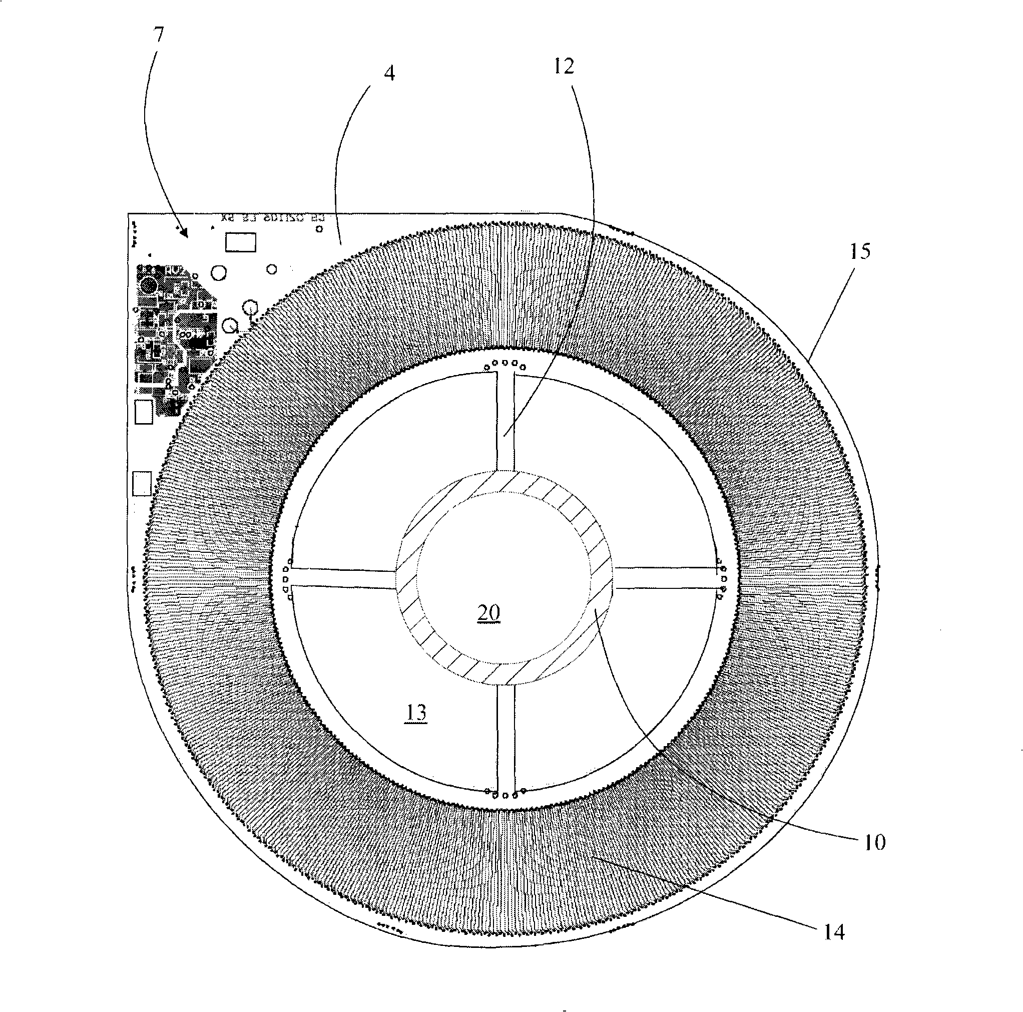
[0033] According to the accompanying drawings, the measuring device, object of the present invention, is generally designated 1 .

[0034] According to the exemplary embodiment illustrated in the accompanying drawings, the device 1 can be operatively connected to a cable line 3, for example three-phase with medium or high voltage, especially for 25 or 36 KV voltage, and can also be applied for low voltage, for measuring A signal indicating the phase voltage and / or current of a power line.

[0035] Advantageously, the device 1 is intended to be used on shielded or bare wires, pylons for circuit breakers, transformers, aerial stations or any other network installations available on the market.

[0036] As will be explained further below, the above-mentioned device 1 is intended not only to be placed on power lines under traction, but also at elastic ends, that is to say the terminations of cables not subjected to mechanical traction, which are normally suitably provided in power...


PUM

PropertyMeasurementUnit
Thicknessaaaaaaaaaa

Abstract

Electrical quantity measuring device for energy transmission line, which is connected with electric line cable or device thereof availably, is comprised of a device for monitoring voltage signal and a device for monitoring current signal. The device for monitoring voltage signal is provided with metallic loop shape throughout capacitance (TV) which is configured coaxially with the cable and can be connected to a capacitor voltage divider. The device for monitoring the current signal is provided at least a current sensor with coil (TA), because the coil is easy to be affected when an induction effect current passing through the coil. The coil is arranged on at least one printed circuit board with central opening, and formed by radiated sediment provided in two surfaces of the printed circuit board and the electric connection of the radiated sediment on the two surfaces. Furthermore, an insulating material layer is provided and is configured to cover the printed circuit board partly; ametallic screen is also designed to cover the printed circuit board partly. The TV and the TA are assembled in an axial manner and merged until forming a unique body in an insulating material matrix,where the matrix delimits a through hole for introducing the cable.

Description

technical field [0001] The invention relates to an electrical quantity, especially voltage and current measuring device for an energy transmission line. [0002] The measuring device of the invention makes it convenient to use in circuit breakers, transformers, power stations or other network installations to provide voltage and / or current values ​​of cables, especially cables near electric towers. [0003] More specifically, the device of the invention is capable of supplying fault signallers with the voltage and current signals necessary for their functioning and preconfiguration of the power line control system. Background technique [0004] It is known that in areas where current is transmitted through high, medium and low voltage lines, there is an increasing need to receive punctual voltage and current information to allow optimal management of power lines and in particular to allow an increasingly efficient operation of faulty sections by remote control of the system ...

Claims


Application Information

Patent Timeline
IPC IPC(8): G01R15/06G01R19/00
Inventor M·伯顿L·米奇卢蒂
Owner С.ДЖ. Э. СОЧИЕТА ДЖЕНЕРАЛЕ ДИ ЭЛЕТТРОНИКА С.Р.Л.
Learn More