Pressure type pump reducing pulsation for vehicle slip control system

A slip control, pressure-type technology, applied in the field of pressure-type pumps, can solve problems such as impact and failure, and achieve the effect of reducing machining time

Inactive Publication Date: 2008-12-24
HYUNDAI MOBIS CO LTD
View PDF0 Cites 2 Cited by
  • Summary
  • Abstract
  • Description
  • Claims
  • Application Information

AI Technical Summary

Problems solved by technology

Due to the reciprocating movement of the plunger of the valve inside the pump, a large number of pulsations are superimposed and increased up to 20 bar, with adverse effects on the relevant components

Method used


Image

  • Pressure type pump reducing pulsation for vehicle slip control system
  • Pressure type pump reducing pulsation for vehicle slip control system

Examples


Embodiment Construction

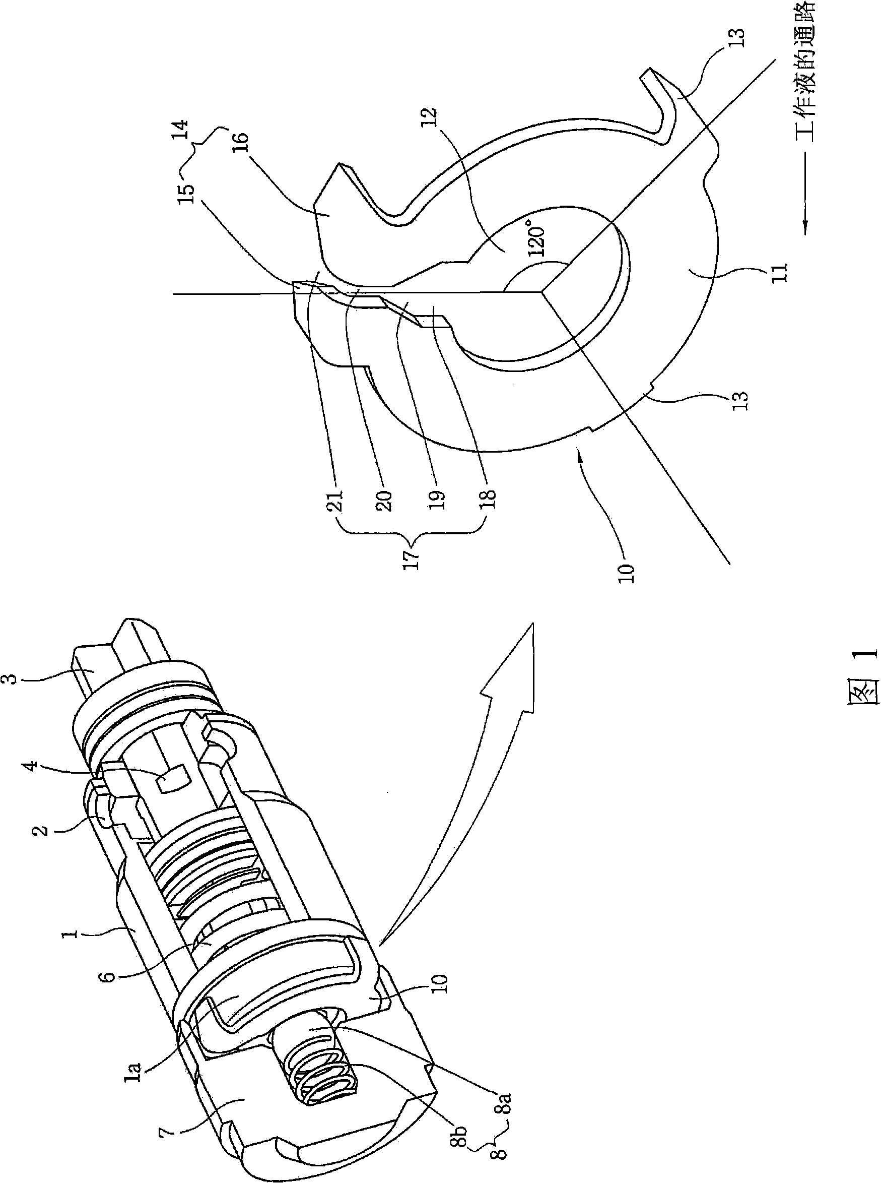
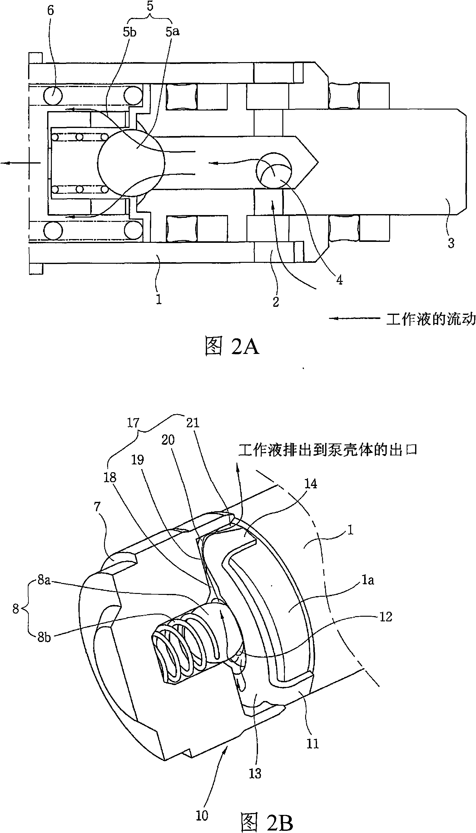
[0023] FIG. 1 is a schematic structural view of an embodiment of a pressure-type pump with reduced pulsation used in a vehicle slip control system according to the present invention. According to an oil control pump of an electronically controlled braking system of the present invention, oil as a working fluid is injected and circulated in the pump, and the pump includes: a bushing 1, a plunger 3, a check valve inlet 5, a check valve Valve outlet 8 and orifice 10. The bushing 1 is fixed on the pump casing and forms a working fluid passage inside it. The plunger 3 is elastically supported by the inner spring 6 in the bushing 1, and allows the working fluid to flow into the pump when the pump is working. The one-way valve inlet 5 is arranged at the front end of the plunger 3 so as to discharge the working fluid into the bushing 1 under the pressure of the working fluid flowing into the plunger 3 . The check valve outlet 8 is accommodated in the cap 7 which is fixed at one end ...


PUM


Abstract

The present invention relates to a pressure pump which is used for reducing the pulse in a vehicle slippage control system. The pressure pump comprises the components of a hollow bush which is fixed on the casing of the pump and a plunger piston that is supported by the internal spring in the bush. The pressure pump also comprises a valve ball which is used for blocking an outlet which is flowed by the working liquid that flows into the plunger piston, a one-way valve spring which is fixed at the outlet of the plunger piston and supports the valve ball, a one-way valve which is fixed on the cover on the plunger piston, a one-way valve outlet which comprises a valve ball and a one-way valve, and a hole component which is provided between the bush and the cap that is fixed at the end part of the bush. The hole piece is provided at a position which discharges the work liquid in the plunger piston to reduce the fluctuating pressure caused by the plunger piston that does reciprocating motion because of the eccentric wheel. Therefore, the fluctuating pressure generated in the pump can be reduced from 20 bar to 5 bar or less.

Description

technical field [0001] The present invention relates to a pump for a vehicle slip control system, and more particularly, to a pressure-type pump with reduced pulsation. Background technique [0002] Generally, vehicle brakes brake or decelerate a vehicle by transmitting brake pressure, which is hydraulic pressure, to wheel brakes based on operation of a brake pedal. As a moving vehicle is forced to a stop by the brakes, the vehicle skids due to brake pressure or road conditions during braking. [0003] A type of brake that electronically controls the braking force on the wheel brakes and is widely used to prevent skidding from occurring. That is, the widespread use of anti-lock braking systems (ABS), traction control systems (TCS) to prevent large slippage of the drive wheels during quick starts or acceleration, or electronic stability program (ESP) systems to reduce the vehicle's ideal driving The difference between the direction and the actual direction of travel, so tha...

Claims


Application Information

Patent Timeline
Patent Type & Authority Applications(China)
IPC IPC(8): F04B9/04F04B7/02
CPCB60T8/4031F04B11/0091B60T8/40F04B17/00
Inventor 金荣圭
Owner HYUNDAI MOBIS CO LTD
Why Eureka
Try Eureka