Articulating dual antenna

A technology for antennas and antenna elements, applied in antennas, folding antennas, rotating antennas, etc., can solve problems such as rough operation of antennas

Inactive Publication Date: 2008-12-17
THOMSON LICENSING SA
View PDF0 Cites 10 Cited by
  • Summary
  • Abstract
  • Description
  • Claims
  • Application Information

AI Technical Summary

Problems solved by technology

[0005] Antennas on portable devices are often handled roughly

Method used


Image

  • Articulating dual antenna
  • Articulating dual antenna
  • Articulating dual antenna

Examples


Embodiment Construction

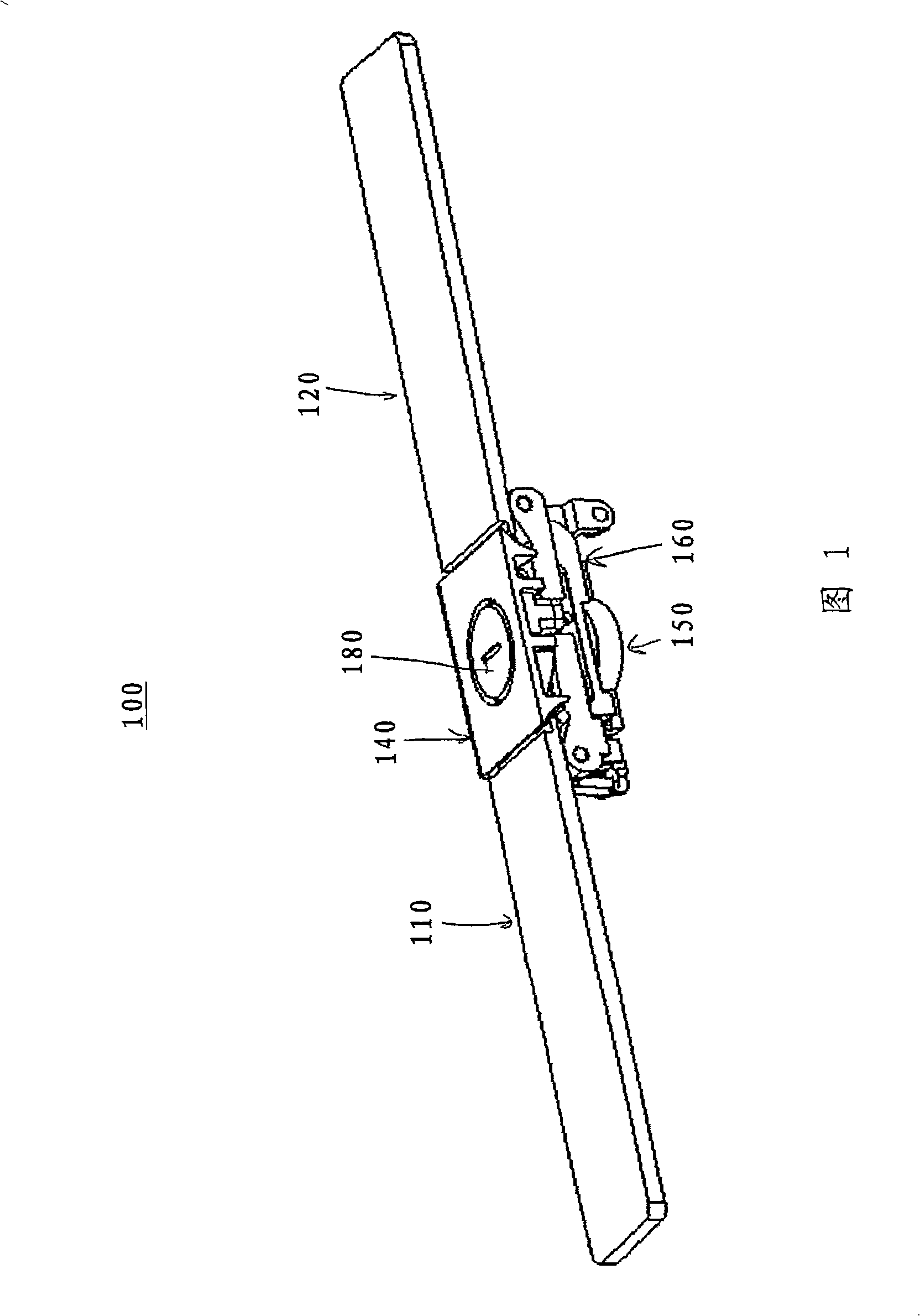
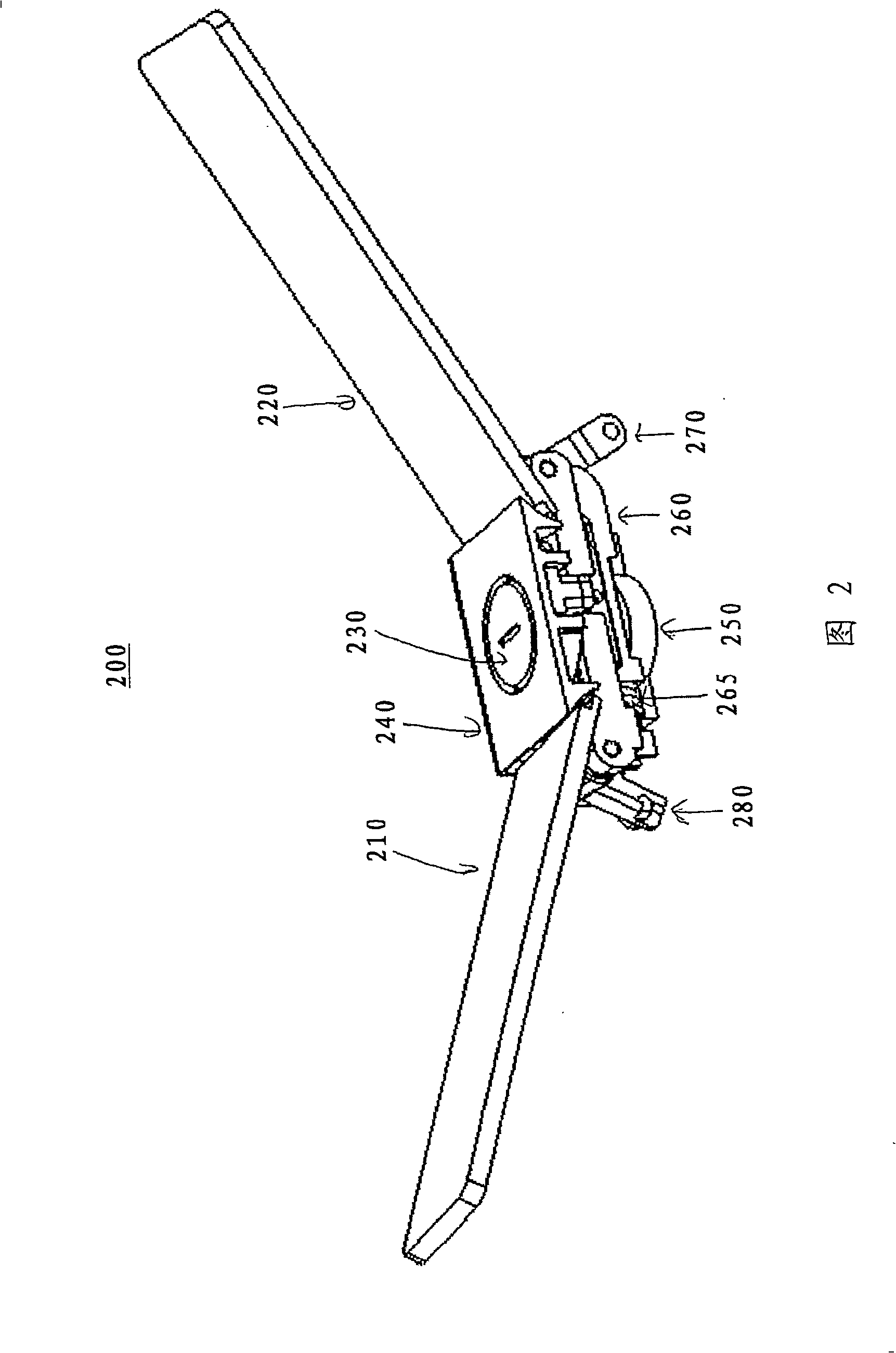
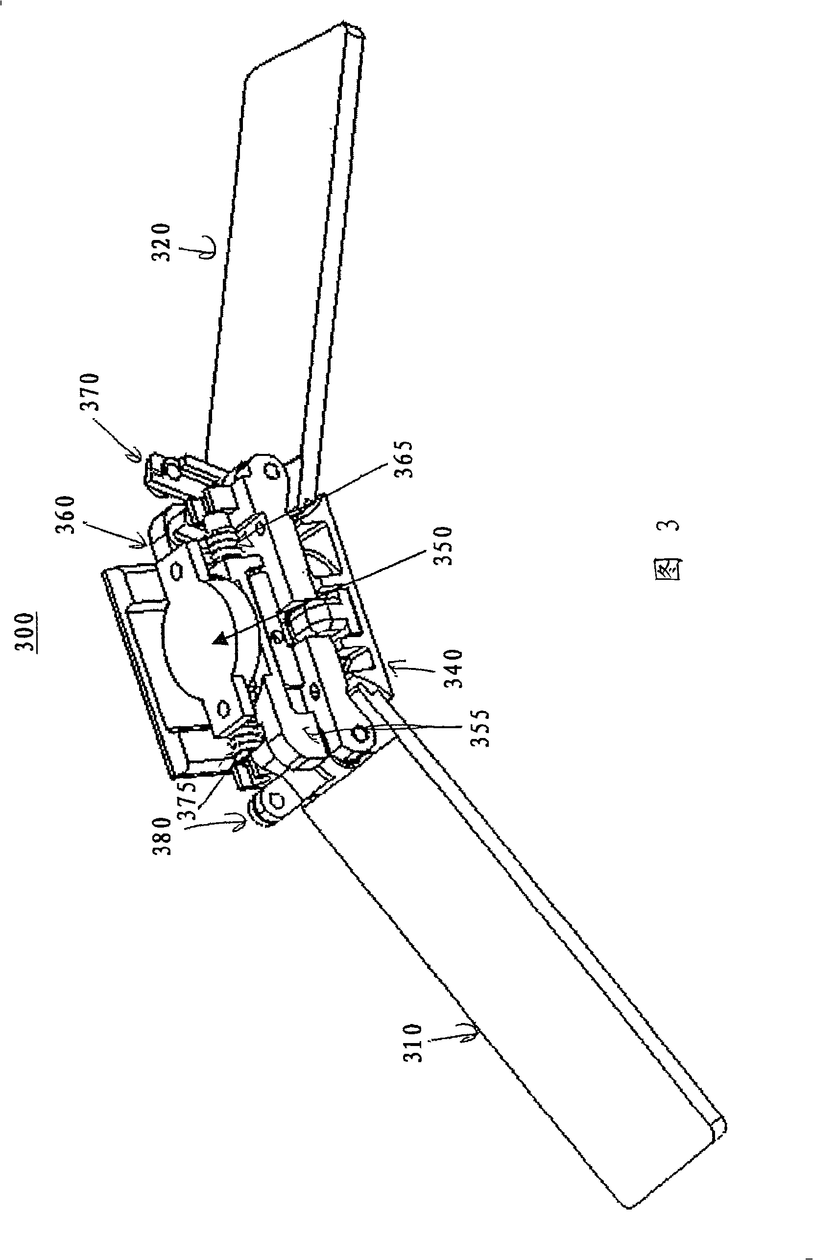
[0013] The preferred embodiment of the present invention teaches a system using two electrically independent antennas coupled by a rack-and-pinion system that constrains the two electrically independent antennas to synchronize them action. Springs preload the system, always biasing the antennas toward their deployed or "up" position. A rotary damper controls the speed at which the antenna is driven to maintain a slow and smooth motion. Pressing down on one or both antennas locks the system closed and both antennas are folded. The system remains in the locked position because the spring-loaded button prevents the pinion from turning until the actuation button is pressed. The button has smooth actuation because it makes contact with the smooth button piston on the end of the button spring. When the button is pressed against the button spring, the button hook moves away from the pinion, allowing the system to be driven open by the antenna spring.

[0014] A further feature of...


PUM


Abstract

A method and apparatus for deploying a multi-element antenna system on a portable television signal processing apparatus. The system utilizes a plurality of spring loaded racks engaged in a pinion restrained by a rotational damper and a manual release mechanism. Each individual rack is attached to a rotational mechanism used to rotate an antenna element around an axis. The springs are compressed when the antenna is in its stored state and released via the manual release mechanism. The released rack and pinion system biases a plurality of rotational mechanisms which respectively extend the antenna elements into their deployed configuration.

Description

[0001] related application [0002] This application claims priority to US Provisional Patent Application No. 60 / 710,940, filed August 24, 2005, entitled "Articulating Dual Antenna," the entire contents of which are hereby incorporated by reference. technical field [0003] The present invention relates to antenna systems for portable electronic devices, and more particularly to deployable antenna systems for portable television signal processing devices. Background technique [0004] Portable television signal processing devices, such as portable television sets and portable radios, are commonly used and antenna systems for these devices are well known. However, since most of these portable devices are designed to receive digital signals, the performance of these antenna systems becomes more demanding and complex. Often these antennas must be more efficient than similar analog antennas, the polarity of the input signal must be more carefully considered, and effects such as...

Claims


Application Information

Patent Timeline
Patent Type & Authority Applications(China)
IPC IPC(8): H01Q3/00H01Q9/28H01Q9/16
CPCH01Q1/08H01Q1/084H01Q1/1235H01Q1/1264H01Q1/2216H01Q3/01H01Q9/12H01Q9/16H01Q3/02H01Q3/00
Inventor 迈克尔·J·肖弗杰西·A·福尔特詹姆斯·R·尤尔琴科戴维·C·汤姆森埃里克·A·多尔西
Owner THOMSON LICENSING SA
Why Eureka
Try Eureka