Wireless dynamic state transmission machine

A transmitter and dynamic technology, applied in signal transmission systems, non-electrical signal transmission systems, instruments, etc., can solve problems such as coal mine safety hazards, signal transmission interruptions, etc., to avoid daily maintenance, reliable safe production, and reliable signal transmission Effect

Inactive Publication Date: 2008-12-17
张正龙
View PDF0 Cites 0 Cited by
  • Summary
  • Abstract
  • Description
  • Claims
  • Application Information

AI Technical Summary

Problems solved by technology

Due to the special environment of the underground coal mine, when the signal cable is damaged due to external force pulling or bumping, the signal transmission will be interrupted, which will bring hidden dangers to the safety of the coal mine. At the same time, the maintenance of the signal cable will also bring many problems to daily work burden

Method used


Image

  • Wireless dynamic state transmission machine
  • Wireless dynamic state transmission machine
  • Wireless dynamic state transmission machine

Examples


Embodiment Construction

[0017] The technical solution will be described in detail below in conjunction with the embodiments.

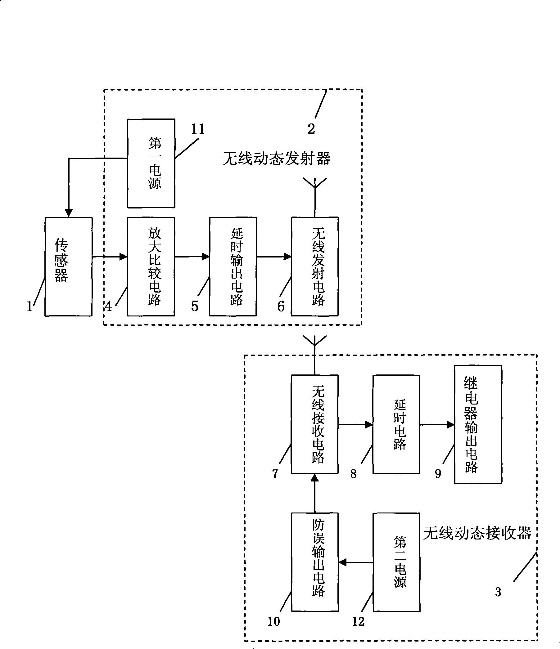
[0018] refer to figure 1 , The wireless dynamic transmitter of the present invention is composed of a sensor 1, a wireless dynamic transmitter 2 and a wireless dynamic receiver 3.

[0019] refer to figure 1 , The wireless dynamic transmitter 2 includes a first power supply 11 , an amplification and comparison circuit 4 , a delay output circuit 5 and a wireless transmission circuit 6 . The amplification and comparison circuit 4 , the delay output circuit 5 and the wireless transmitting circuit 6 are connected to the sensor 1 in sequence.

[0020] The main circuits in the wireless dynamic transmitter 2 will be described below.

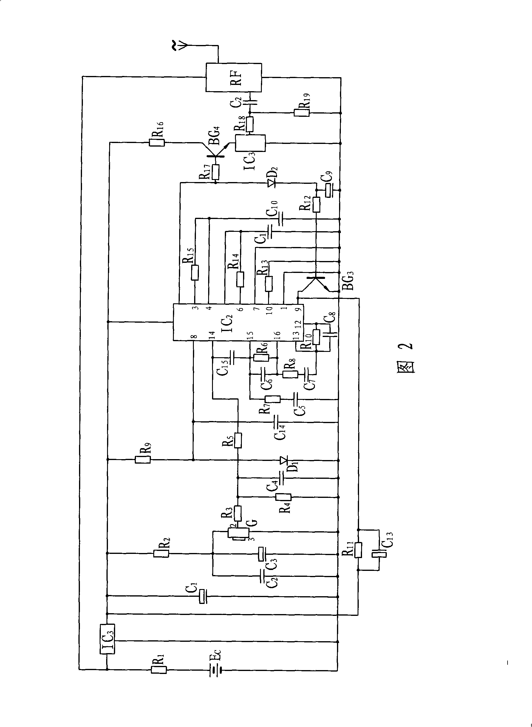
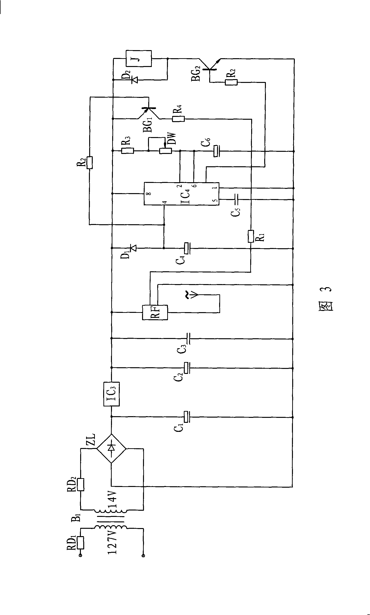
[0021] refer to figure 1 and Figure 2, where the power supply Ec as the first power supply 11 passes through R 1 The intrinsically safe voltage and current of the current-limited output are divided into two paths, one path is directly supplied to t...


PUM


Abstract

The invention relates to a wireless dynamic transmission device which comprises a sensor, a wireless dynamic transmitter and a wireless dynamic receiver. The wireless dynamic transmitter comprises a first power source, an amplifying comparison circuit, a time-delay output circuit and a wireless transmitting circuit; and the wireless dynamic receiver comprises a second power source, a wireless receiving circuit, a time-delay circuit and a relay circuit. The output signal of the sensor is wirelessly transmitted to the wireless dynamic receiver through the wireless dynamic transmitter, and the relay circuit sends control signals to a subsequent controller. The wireless dynamic transmission device has the advantages as follows: because wireless reception and transmission are two independent units, signal transmission between the both is realized by adopting a radio wave, thereby eliminating signal connecting cables, avoiding the damage and the routine maintenance of the signal cables, and effectively ensuring the smooth transmission of the signals. Through the field simulation test, the wireless dynamic transmission device has the advantages that the signal transmission is reliable, the control action is sensitive, the operation is convenient, the performance is sufficient for satisfying the practical application, and the wireless dynamic transmission device provides reliable guarantee for the safe production of coal mines.

Description

technical field [0001] The invention relates to a control device, in particular to a wireless dynamic transmitter. Background technique [0002] At present, in the equipment used in underground coal mines, the control part and the sensor part mostly adopt the method of connecting cables to transmit signals. If the control part and the sensor part of the equipment are far apart, many cables need to be laid. Due to the special environment of the underground coal mine, when the signal cable is damaged due to external force pulling or bumping, the signal transmission will be interrupted, which will bring hidden dangers to the safety of the coal mine. At the same time, the maintenance of the signal cable will also bring many problems to daily work burden. In order to solve the above problems, it is urgent to innovate the transmission technology of underground equipment in coal mines. Contents of the invention [0003] The purpose of the present invention is to provide a wirel...

Claims


Application Information

Patent Timeline
Patent Type & Authority Applications(China)
IPC IPC(8): G08C17/02G08C17/00G08C23/04
Inventor 张正龙
Owner 张正龙
Why Eureka
Try Eureka