
Stretching assembly of elevator apparatus

A technology of stretching components and elevators, which is applied to elevators, textile cables, transportation and packaging in buildings, etc., and can solve problems such as increased complexity of system layout, loud car noise, and meshing noise

Active Publication Date: 2008-12-17
SHANGHAI MITSUBISHI ELEVATOR CO LTD
View PDF3 Cites 7 Cited by
  • Summary
  • Abstract
  • Description
  • Claims
  • Application Information

AI Technical Summary

Problems solved by technology

First, there is meshing noise between the rope and the traction sheave
Secondly, due to the small diameter of the rope core, it is necessary to increase the number of ropes in the elevator system, which leads to an increase in the complexity of the system layout
Moreover, as the number of ropes increases, the vibration of the ropes is more obvious, so the vibration transmitted to the elevator car increases accordingly, resulting in greater noise in the car
Thirdly, the contact pressure between the rope and the traction sheave increases, resulting in an increase in the contact pressure between the inclusion and the rope core, which reduces the life of the inclusion and the rope core and affects the life of the rope

Method used


Image

  • Stretching assembly of elevator apparatus
  • Stretching assembly of elevator apparatus

Examples


Embodiment 1

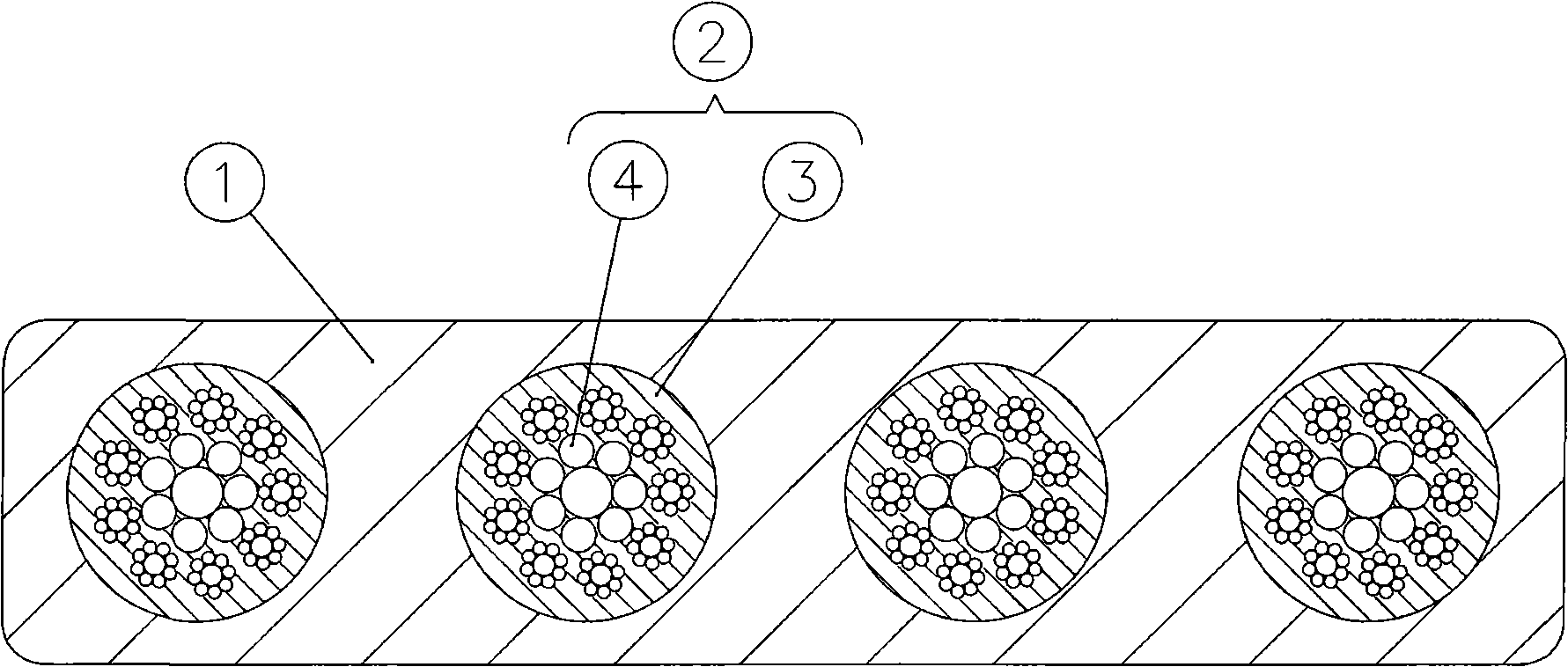
[0020] see figure 1 As shown, the tensile assembly includes a wrapping body 1 and a carrier body 2 , and the carrier body 2 is composed of a coating layer 3 and a carrier core wire 4 . There are 9 strands on the periphery of the load-bearing core wire 4 . In the center of the load-bearing core wire 4 there is a strand. Each strand of the carrying core wire 4 is formed by parallel twisting of a plurality of metal core wires. In this way, the contact between the metal core wires of each strand is a line contact, so the contact stress between the metal core wires is reduced. At the same time, the carrying core wire 4 can maintain a good shape. In order to improve the bending fatigue strength of the load-bearing core wire 4, the metal core wire is required to be relatively thin, about 0.15-0.6 mm. In addition, in order to further increase the bending fatigue life of the load-bearing core wire 4 , the ratio of the diameter of the load-bearing core wire 4 to the diameter of the ...

Embodiment 2

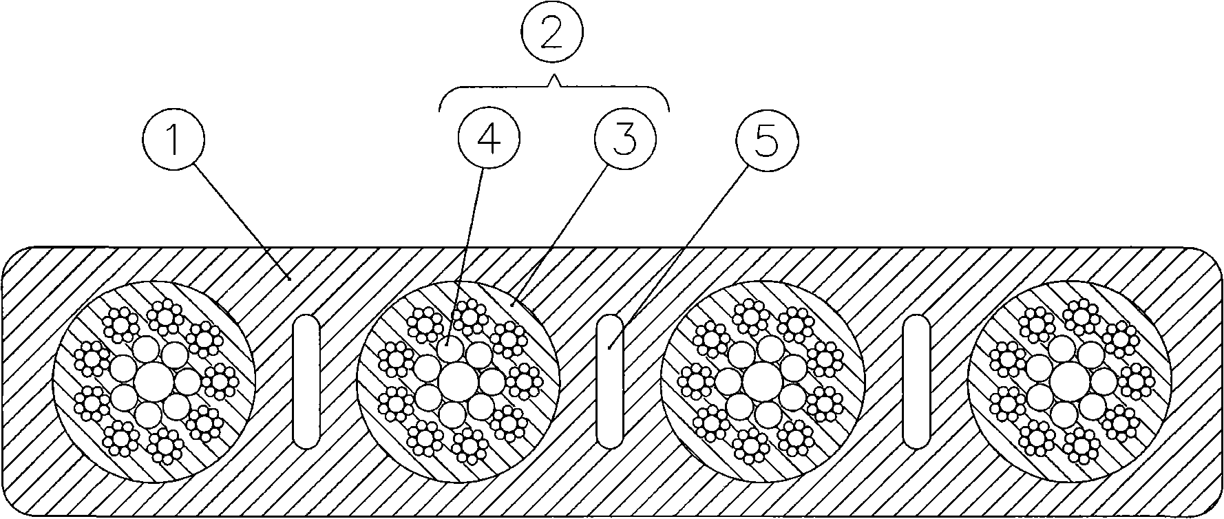
[0030] see figure 2 As shown, the difference from the first embodiment is that three holes 5 are provided in this embodiment. Holes 5 are located between adjacent carriers 2 . The effect of the hole 5 is that the arrangement between the stretching assembly and the traction pulley and the anti-sheave does not necessarily have to be parallel. Because the hole 5 can eliminate the internal stress on the inclusion 1 when the stretching assembly is not parallel to the arrangement of the traction sheave and the anti-sheave. Thus does not affect the life of the tensile components.


PUM

PropertyMeasurementUnit
Diameteraaaaaaaaaa
Strengthaaaaaaaaaa
Tensile strengthaaaaaaaaaa

Abstract

The invention discloses a stretching component of elevator devices, and comprises a plurality of supporting bodies that have clad and support core wires and an including body that includes the supporting body, wherein, the including body takes a shape of a flat zonal body structure, and the width of the including body is at least larger than the thickness of the including body; the clad of the supporting body and the including body are made of non-metallic materials, and the supporting body and the including body can move relatively. The stretching component of the invention can eliminate the deformation influence of the including body, improves the service life of the stretching component, has the advantages of simple structure, long service life and good friction property, etc., and leads elevator systems to be more flexible.

Description

technical field [0001] The invention relates to a tensioning assembly for traction elevator installations. Background technique [0002] In conventional elevator installations driven by traction sheaves, the tensile components are steel wire ropes. There are certain restrictions on the use of wire ropes, such as the limitation of the traction force between the wire rope and the traction pulley, the requirements on the bending performance and fatigue performance of the wire rope. Due to the limitation of the traction force, in order to increase the traction force, it is often necessary to increase the wrap angle between the wire rope and the traction pulley, or to slot the traction pulley. This will reduce the life of the wire rope. At the same time, due to the requirements of the bending performance and fatigue performance of the wire rope, the minimum diameter of the wire rope is 8mm (GB7588-2003 standard), and the diameter of the traction pulley is at least 40 times the ...

Claims


Application Information

Patent Timeline
IPC IPC(8): D07B1/22D07B5/00B66B11/00
CPCD07B1/0686D07B1/22D07B2501/2007
Inventor 周双林甘靖戈
Owner SHANGHAI MITSUBISHI ELEVATOR CO LTD
Learn More