
Multifunction tiller

A cultivator and multi-functional technology, applied in the field of ditch clearing, intertillage cultivator, and ridging, it can solve the problems of unsatisfactory operation effect, high labor intensity, and large change of moisture content.

Inactive Publication Date: 2008-12-17
张培坤
View PDF1 Cites 5 Cited by
  • Summary
  • Abstract
  • Description
  • Claims
  • Application Information

AI Technical Summary

Problems solved by technology

Manual work has low labor efficiency, high labor intensity, and high production costs, which cannot meet the requirements of modern production development; field tillage machines are used for ditch clearing and intertillage soil cultivation due to the different widths of trenches, large changes in soil quality and soil moisture content, and the machine tool itself. Structural defects make it have shortcomings such as less soil cultivation, inadequate soil cultivation, untidy trenches, and inability to intertill and weeding, and the operation effect is not ideal
[0003] Chinese utility model patent 200520111134.7 discloses a single-wheel, intertillage, and universal cultivator, which is provided with a fuselage, a handle, a diesel engine, a clutch, a reducer, a herringbone wheel, and a head, and the diesel engine is fixed on the front of the fuselage. The power output pulley of the diesel engine is connected to the clutch by a V-belt. The power output connecting rod of the clutch is equipped with a worm gear reducer. There are two operating handles attached to the rear of the fuselage. Although the above-mentioned cultivator is small in size and easy to operate, it is not suitable for intertillage operations on convex ridges, and is not suitable for tobacco leaves, potatoes, etc. , taro, and other crops

Method used


Image

  • Multifunction tiller
  • Multifunction tiller
  • Multifunction tiller

Examples


Embodiment Construction

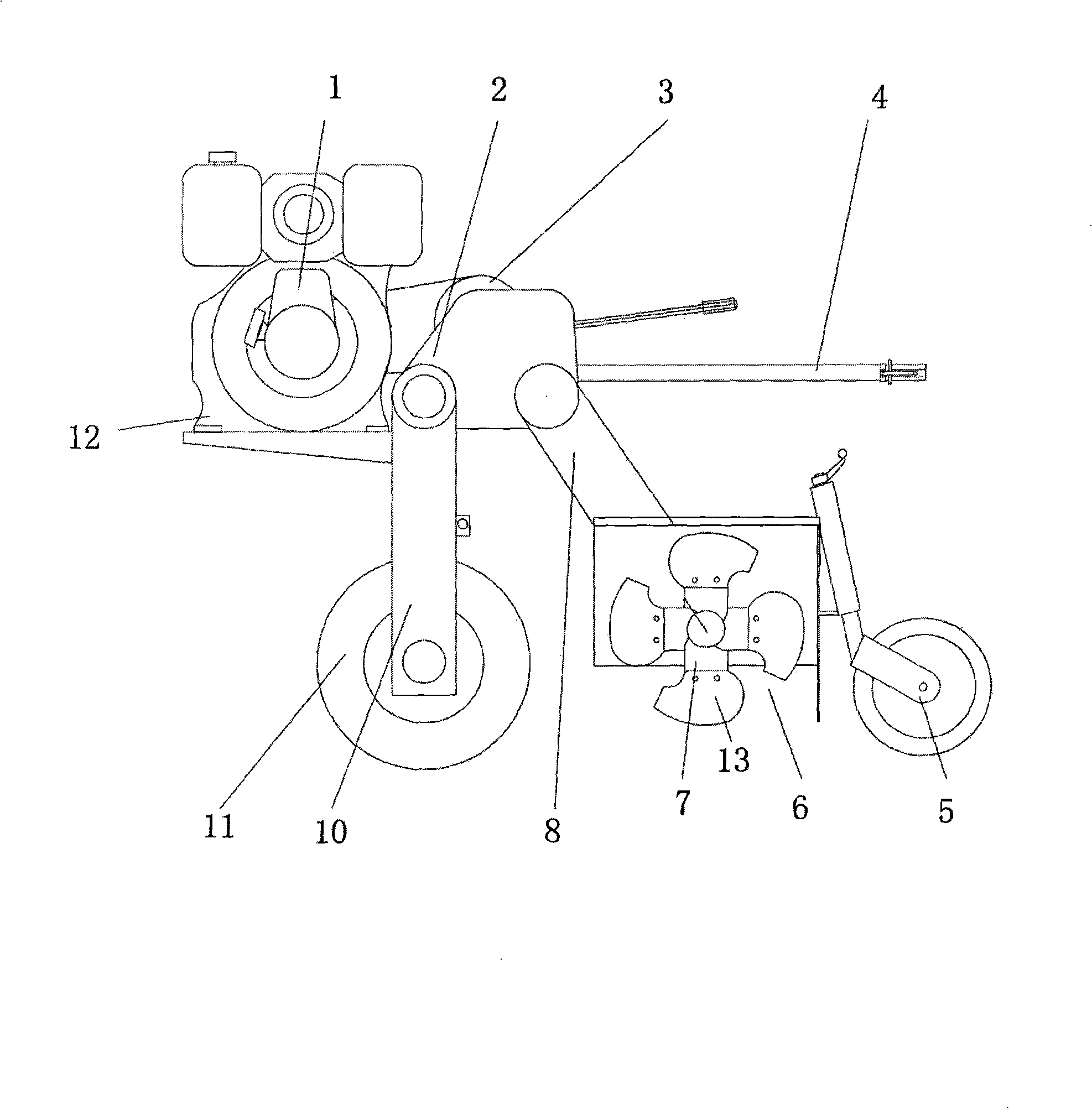
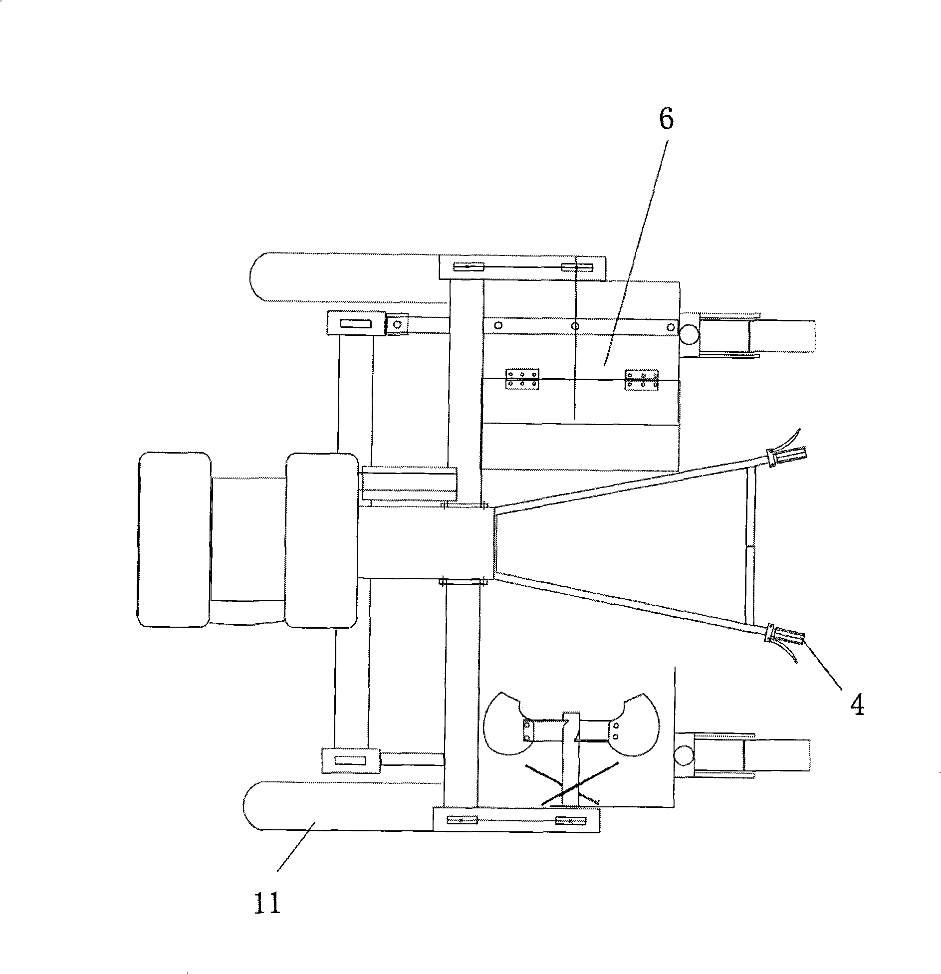
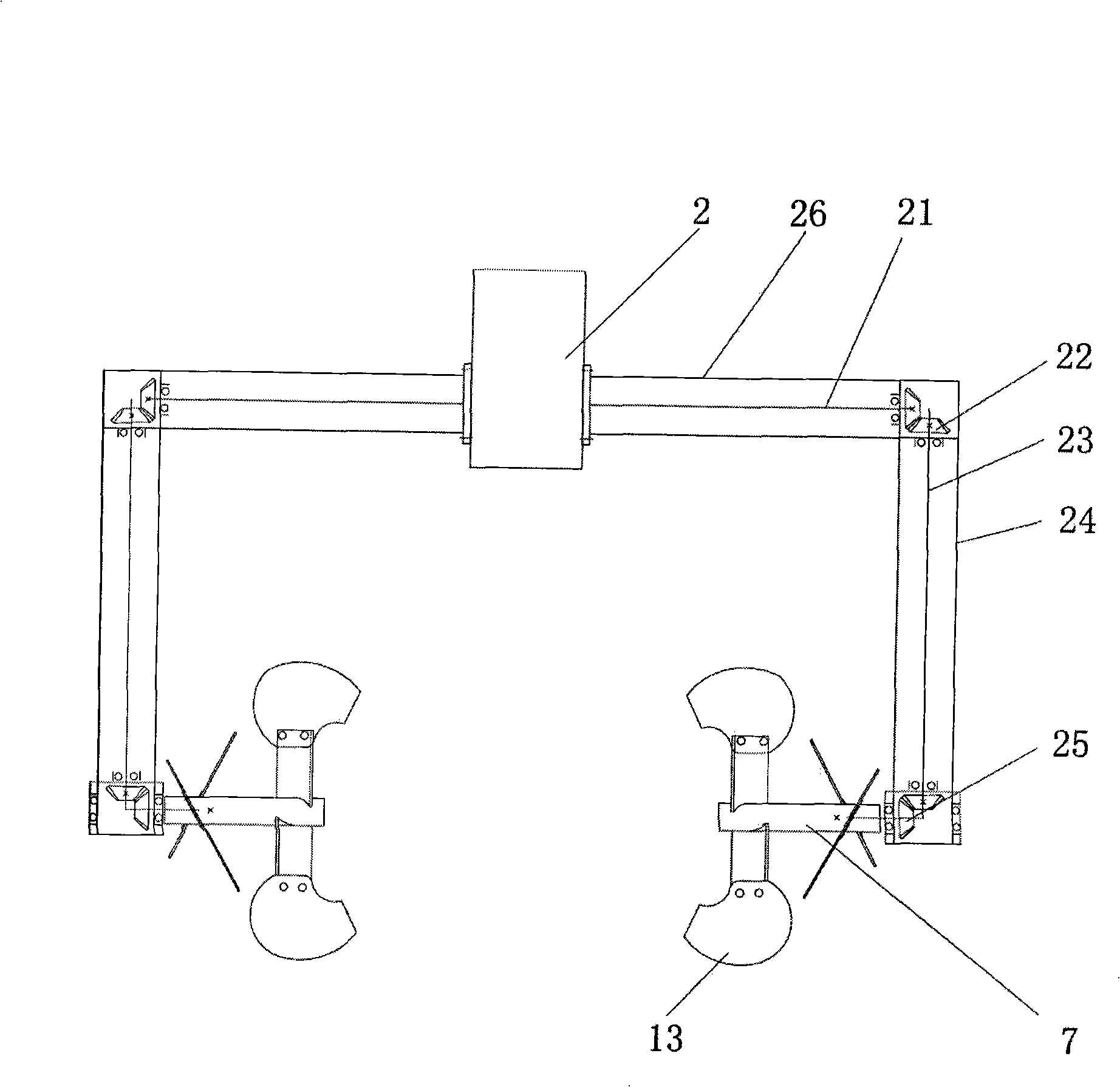
[0039] see figure 1 and figure 2 A multifunctional cultivator, comprising a fuselage 12, an engine 1, a gearbox 2, an armrest frame 4, a coulter 13 and a soil guide scraper 6, the engine 1 is fixed in front of the fuselage 12, and the engine 1 is connected to the gearbox 2 , the gearbox 2 is provided with a clutch 3, the armrest frame 4 is connected with the gearbox 2, and the gearbox respectively drives the coulter transmission mechanism 8 and the driving wheel transmission mechanism 10, and the coulter transmission mechanism 8 drives the coulter 13, and the coulter transmission mechanism 8 drives the coulter 13, and the coulter The knife is two independent coulters, which are respectively located on both sides of the fuselage; the driving wheel transmission mechanism 10 drives the driving wheel 11; the end of the coulter transmission mechanism is provided with a soil guide scraper 6, and the soil guide scraper is fixed on the On the rotor side, the coulter transmission mec...


PUM


Abstract

The invention discloses a multifunctional tillage machine, comprising a machine body, an engine, a transmission case, a handrail rack, a coulter and a soil guiding scraper. The engine respectively drives a transmission organ of the coulter and a transmission organ of a driving wheel by the transmission case. The transmission organ of the coulter drives the coulter, and the transmission organ of the driving wheel drives the driving wheel; the end of the transmission organ of the coulter is provided with the soil guiding scraper; both the transmission organ of the coulter and the transmission organ of the driving wheel are vertical type transitional transmission organs; the coulter is composed of two independent coulters respectively positioned at both sides of the machine body. The tillage machine of the invention has a high chassis, thereby having convenience to have ride work on the farmland ridge growing with crops, being capable of not only high-efficiently finishing plowing preparation work such as ridge forming, ditch cleaning, and the like, but also carrying out cultivating and banking in the growing process of crop so as to be an ideal tillage implement of crops such as tobacco leaf, potato, taro, cane, etc. Simultaneously, the multifunctional tillage machine provides an ideal work platform and source of power for small watering machines and small fertilizer machineries.

Description

technical field [0001] The invention relates to the field of agricultural machinery, in particular to a cultivator suitable for ridging, ditch clearing and cultivating soil in convex ridges. Background technique [0002] Existing ridging, ditch clearing, intertillage and soil cultivation operations in my country's rural agricultural production are mainly carried out by hand or with pastoral tillage machines. Manual work has low labor efficiency, high labor intensity, and high production costs, which cannot meet the requirements of modern production development; field tillage machines are used for ditch clearing and intertillage soil cultivation due to the different widths of trenches, large changes in soil quality and soil moisture content, and the machine tool itself. Due to the structural defects of the plant, there are shortcomings such as less soil cultivation, inadequate soil cultivation, untidy trenches, and inability to intertill and weeding, and the operation effect ...

Claims


Application Information

Patent Timeline
IPC IPC(8): A01B33/16A01B33/08A01B33/12
Inventor 张培坤
Owner 张培坤
Learn More