
Thermal power unit coal-burning thermal value real time monitoring method and thermal value observer

A technology of thermal power unit and coal-fired calorific value, applied in instruments, simulators, computer control, etc., can solve problems such as difficult and difficult boiler combustion dynamic characteristics, without considering boiler animal heat energy, etc., to avoid over-temperature and over-pressure, The effect of fast response and great flexibility

Active Publication Date: 2008-12-10
CHINA ELECTRIC POWER RES INST +2
View PDF0 Cites 20 Cited by
  • Summary
  • Abstract
  • Description
  • Claims
  • Application Information

AI Technical Summary

Problems solved by technology

The disadvantage of this method is: coal enters the furnace and burns is a high-order inertial link with pure delay, and its delay time and inertia time vary with the combustion conditions of the boiler. Using the third-order inertial link It is difficult to express the dynamic characteristics of boiler combustion well, which is very difficult in real operation
In addition, this method only calculates the output energy of the boiler, without considering the heat energy of the boiler
Therefore, there are certain deficiencies in this method, and it cannot be implemented and applied well in practical applications.

Method used


Image

  • Thermal power unit coal-burning thermal value real time monitoring method and thermal value observer
  • Thermal power unit coal-burning thermal value real time monitoring method and thermal value observer
  • Thermal power unit coal-burning thermal value real time monitoring method and thermal value observer

Examples


Embodiment Construction

[0016] The present invention will be described in detail below in conjunction with the accompanying drawings and embodiments.

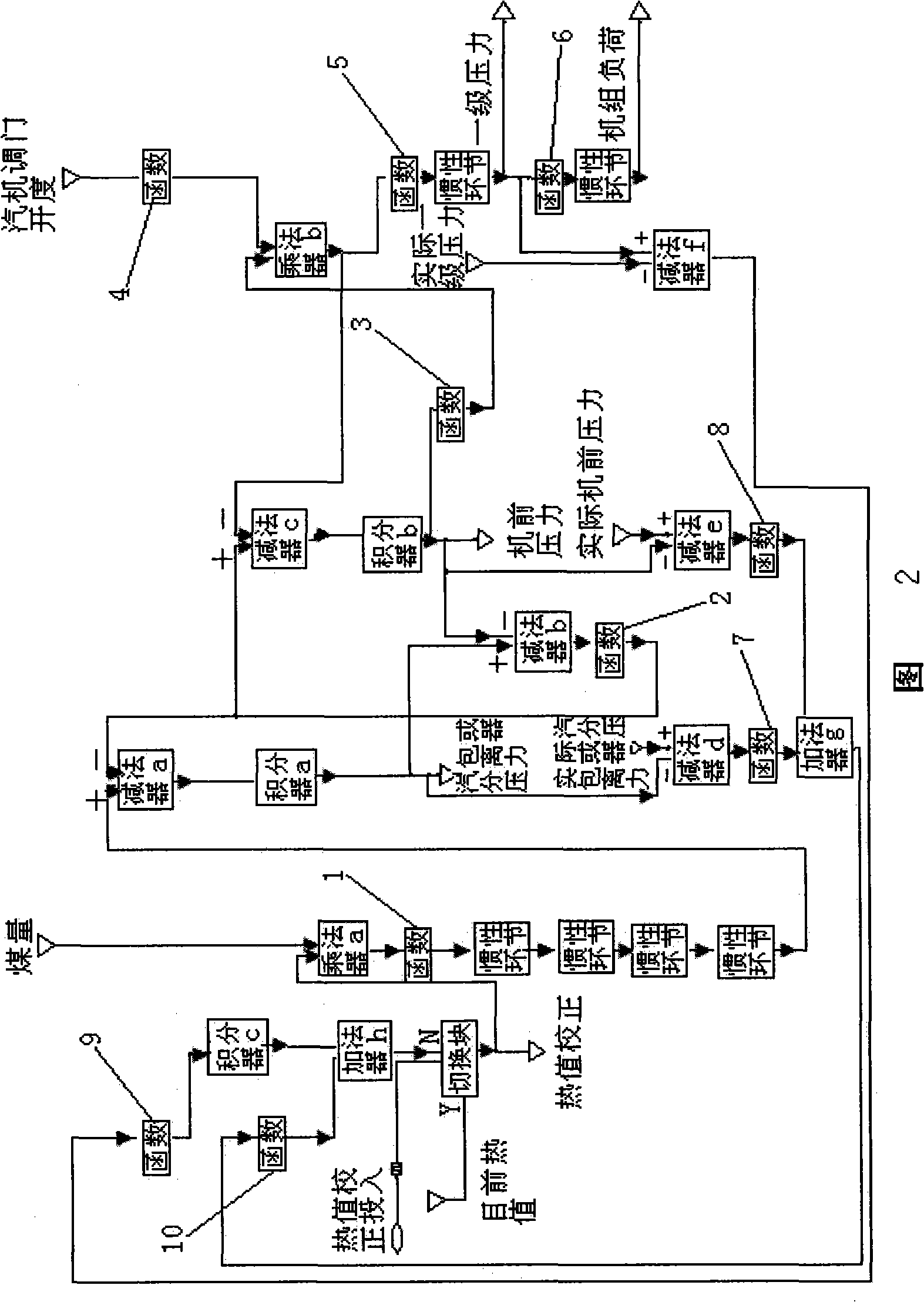
[0017] As shown in Figure 2, the calorific value observer of the present invention is established based on the dynamic characteristics of thermal power units and using the law of energy conservation. It includes two parts: the unit model and the calorific value correction loop. The unit model includes a group of function generators 1 to 6. The input terminal of function generator 1 is connected to a multiplier a, and its output terminal is input to the + input terminal of subtractor a after passing through four inertia links. One input of the multiplier a is connected to the calorific value correction circuit, and the other input is the amount of coal. The input variable of the function generator 1 is the coal volume corrected by the calorific value, and its output is the intermediate reference variable - the main steam flow rate. Its function is to c...


PUM


Abstract

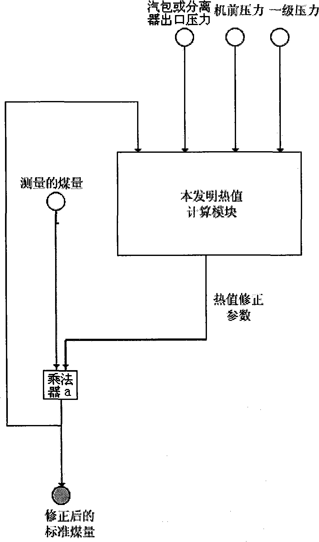
The invention relates to a thermal power unit coal heat value real-time monitoring method and a heat value observer thereof. The invention comprises the following steps: 1) based on the dynamic characteristics of the thermal power unit, the heat value observer is established by the energy conservation law; 2) during the stable operation of an actual operating unit under the conditions of the designed coal rank and various loads, the corresponding relation among all the operation parameters of the actual operating unit can be searched in a DCS control system; 3) according to the probability statistics on the operation parameters of the actual operating unit, the static configuration and the dynamic configuration of the parameters of the unit model are carried out, and thus the unit model can be perfectly matched with the actual operating unit; 4) according to the coal consumption signal which is measured in site and the current operation parameters of the unit, the heat value observer can get a heat-value modified parameter through calculation, and the modified parameter can modifies the coal consumption signal in site to obtain the standard coal consumption signal. The application in site shows that the monitoring method and the observer can perfectly make the online real-time monitoring of the changes of the coal heat value, and thus the control system can perfectly overcome the interference on the boiler combustion due to the coal quality variation.

Description

technical field [0001] The invention relates to a method and device for monitoring the calorific value of coal combustion, in particular to a method for real-time monitoring of the calorific value of coal combustion of a thermal power unit and a calorific value observer applied in the field of automatic control. Background technique [0002] With the continuous development of my country's electric power industry, the power generation capacity of the unit thermal power generation unit has also been greatly improved, from the original 300MW subcritical unit to 600MW supercritical and 1000MW ultra-supercritical. With the improvement of unit parameters, higher requirements are put forward for the automatic control of power plants. In power plant automation control, fuel control is the most basic control part, and the effect of fuel control directly affects the control level of the whole unit. The high energy consumption of power generating units and coal mining have formed a cu...

Claims


Application Information

Patent Timeline
IPC IPC(8): G05B19/048G06G7/26
Inventor 韩忠旭周传心李丹
Owner CHINA ELECTRIC POWER RES INST
Learn More