Load bearing spring of vibration rotary frame for discharging tin of ceramic mould

A ceramic mold and rotating frame technology, applied in the field of load-bearing springs, can solve the problems of inconvenient installation and demolition, no comparison documents are found, etc., and achieve the effect of convenient installation and demolition and simple structure.

Inactive Publication Date: 2008-12-10
SOUTHWEST JIAOTONG UNIV
View PDF0 Cites 0 Cited by
  • Summary
  • Abstract
  • Description
  • Claims
  • Application Information

AI Technical Summary

Problems solved by technology

A vibration buffer zone is established between the substrate and the base of this structure, so that the exciter will not drive the ground to vibrate violently during operation, thereby improving the working efficiency of the exciter, saving energy, and reducing noise. Very inconvenient
[0003] After searching, no other comparative documents related to solving this kind of problem were found

Method used


Image

  • Load bearing spring of vibration rotary frame for discharging tin of ceramic mould

Examples


Embodiment Construction

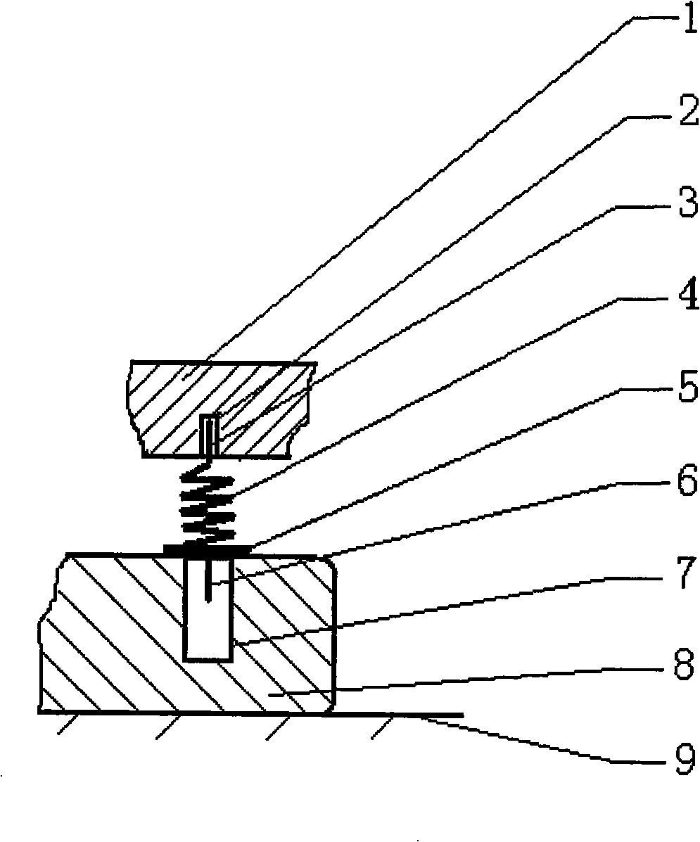
[0010] The vibrating rotary frame for ceramic mold tin discharge provided by the present invention has multiple load-bearing springs, including a spring body 4, a threaded connecting rod 3, a seat ring 5, and a positioning rod 6, wherein the vibratory rotary frame for ceramic mold tin discharge includes a base 1 and base plate 8; threaded hole 2 is arranged on base 1; positioning hole 7 is arranged on base plate 8, is fixed on the ground 9; threaded connecting rod 3 is fixed on the upper end of spring body 4 and is connected with spring body 4 as a whole; The lower end of the spring body 4 is connected as a whole with the spring body 4, and its aperture is greater than the aperture of the positioning hole 7; the positioning rod 6 is fixed at the center of the seat ring 5 and is connected as a whole with the seat ring 5, and is paid out downwards. In addition, the method of fixing the base plate 8 on the ground 9 includes cement seat fixing and screw fixing, which is common sens...


PUM


Abstract

The invention discloses bearing springs of a shaking rotating rack for the tin discharge of a ceramic die. Each spring comprises a spring body, a thread connecting rod, a seat ring and a location pin, wherein the shaking rotating rack for the tin discharge of the ceramic die comprises a base and a base plate. The base is provided with thread holes, and the base plate which is provided with location holes are fixed on the ground. The thread connecting rod is fixed on the upper end of the spring body; the seating ring is fixed on the lower end of the spring body, and the aperture of the seating ring is larger than that of one location hole; the location fixed by a pin in the center of the seating ring is extended downwardly. The bearing springs of the shaking rotating rack for the tin discharge of the ceramic die have a simple structure. When in use, the bearing springs can form a shock buffer area between the base plate and the base, and simultaneously make the whole structure more convenient during assembling and disassembling. The bearing springs are suitable for ceramic die manufacturing.

Description

technical field [0001] The invention relates to a load-bearing spring, in particular to a load-bearing spring for a vibrating rotary frame used when tinning is discharged from a ceramic mold. Background technique [0002] Ceramic molds, especially isostatic ceramic molds, need to be filled with tin when processing the isostatic film, and after the isostatic film is processed, tin needs to be discharged from the isostatic cavity through the tin discharge hole. Due to the heavy weight of the isostatic ceramic mold, the traditional method of removing tin by artificial shaking not only results in incomplete tin removal, but also inefficiency. In the patent "spring footing of vibrating rotary frame for ceramic mold tin discharge" applied at the same time as the present invention, its basic structure has been given including a base plate and a load-bearing spring, wherein the base plate is fixed on the ground; the load-bearing spring has 2 to There are 5 rows, each row has 2 to 5...

Claims


Application Information

Patent Timeline
Patent Type & Authority Applications(China)
IPC IPC(8): C04B35/638
Inventor 张继业曹宇张克跃
Owner SOUTHWEST JIAOTONG UNIV
Why Eureka
Try Eureka