Wall surface cleaning robot based on positive-negative pressure adsorption principle
A cleaning robot, positive and negative pressure technology, applied in the direction of cleaning machinery, cleaning equipment, carpet cleaning, etc., can solve the problems of complex structure, poor adsorption effect on the wall, poor obstacle surmounting ability, etc., to achieve good adsorption effect and good obstacle surmounting ability , the effect of simple structure
- Summary
- Abstract
- Description
- Claims
- Application Information
AI Technical Summary
Problems solved by technology
Method used
Image
Examples
specific Embodiment approach 1
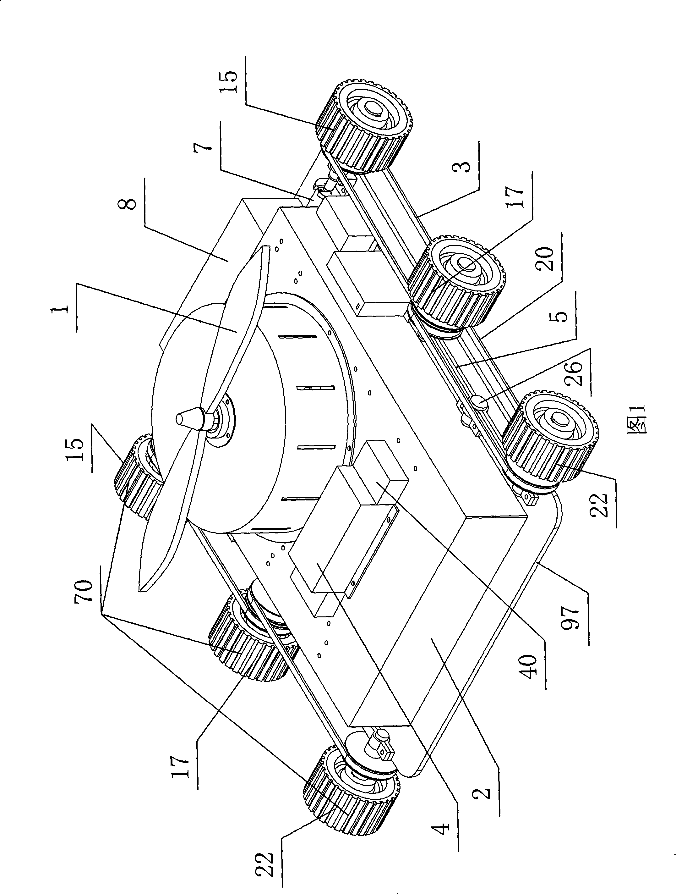
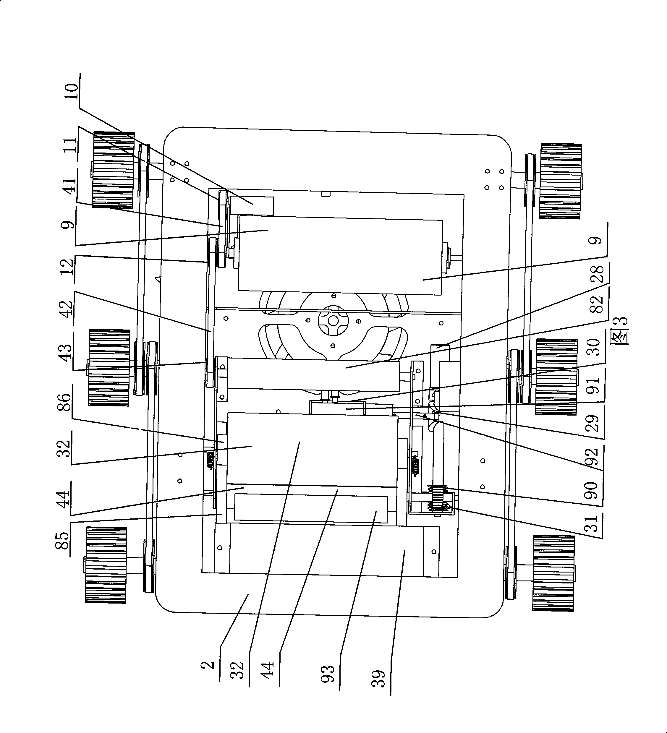
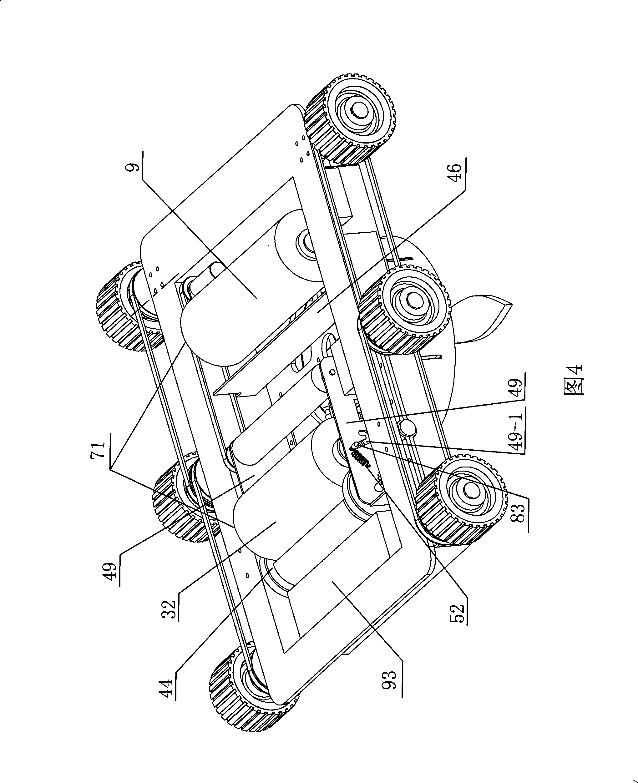
[0008] Specific Embodiment 1: As shown in Figures 1 to 7, the wall cleaning robot based on the principle of positive and negative pressure adsorption described in this embodiment includes a housing 2, a three-phase motor 13, a propeller 1, a centrifugal blade 23, a wheeled walking System 70, cleaning mechanism 71 and water inlet and outlet mechanism 72, cleaning mechanism 71 and water inlet and outlet mechanism 72 are installed in the housing 2, wheeled walking system 70 is installed in the lower part of the housing 2, and the cleaning mechanism 71 includes a dry brush 9 , wet brush 27, water suction roller 32, water squeezing roller 44, dry brush shaft 81, wet brush shaft 82, water suction roller shaft 83, water squeezing roller shaft 84, two driving wheels 85, two driven wheels 86, sewage collection box 39. Sewage collection container 93, motor 10, first pulley 11, second pulley 12, third pulley 43, first transmission belt 41 and second transmission belt 42; 28. Composed of ...
specific Embodiment approach 2
[0009] Specific Embodiment 2: As shown in Figures 1-2, the wheeled walking system 70 in this embodiment is composed of two sets of wheeled walking assemblies, and the two sets of wheeled walking assemblies are respectively installed on the outside of the housing 2. Along the top, each wheeled travel assembly is composed of an adjustable motor 7, a front wheel 15, a middle wheel 17, a rear wheel 22, a support rod 5, a pin 26, a first synchronous belt 3 and a second synchronous belt 20, The adjustable motor 7 is mounted on the front end of the housing 2, and the middle part of the support rod 5 is rotationally connected with the outer edge of the housing 2 through a pin 26. The output shaft of the adjustable motor 7 is rotationally connected with the front wheel 15, and the front wheel 15 The first synchronous belt 3 is connected with the middle wheel 17, and the middle wheel 17 is connected with the rear wheel 22 by the second synchronous belt 20. The middle wheel 17 is installe...
specific Embodiment approach 3
[0010] Specific implementation mode three: as shown in Figure 1 and Figure 9 As shown, the wheeled walking system 70 in this embodiment is composed of two front driving wheels 45, two rear driven wheels 50, two synchronous belts 51, and two reduction motors 47, and the two reduction motors 47 are respectively installed On the two side walls of the front end in the housing 2, the two front driving wheels 45 are respectively connected in rotation with the output shafts of the two reduction motors 47, and the two rear driven wheels 50 are installed on the two side walls of the rear end in the housing 2 respectively. Above, the two front driving wheels 45 and the two rear driven wheels 50 are respectively connected by two synchronous belts 51 . This embodiment is a four-wheel drive, and the four wheels are all installed inside the housing 2 and driven by two reduction motors 47, which can realize forward, backward and turning. This embodiment can make the structure simpler and m...
PUM
 Abstract
Description
Claims
Application Information
 - Generate Ideas
- Intellectual Property
- Life Sciences
- Materials
- Tech Scout
- Unparalleled Data Quality
- Higher Quality Content
- 60% Fewer Hallucinations
Browse by: Latest US Patents, China's latest patents, Technical Efficacy Thesaurus, Application Domain, Technology Topic, Popular Technical Reports.
© 2025 PatSnap. All rights reserved.Legal|Privacy policy|Modern Slavery Act Transparency Statement|Sitemap|About US| Contact US: help@patsnap.com


