
Optical multipurpose image detecting structure

A multi-purpose, optical technology, applied in the direction of instrumentation, electrical digital data processing, input/output process of data processing, etc., can solve problems such as inability to obtain displacement data, inability to capture displacement data, etc.

Inactive Publication Date: 2008-11-26
PACING TECH
View PDF1 Cites 3 Cited by
  • Summary
  • Abstract
  • Description
  • Claims
  • Application Information

AI Technical Summary

Problems solved by technology

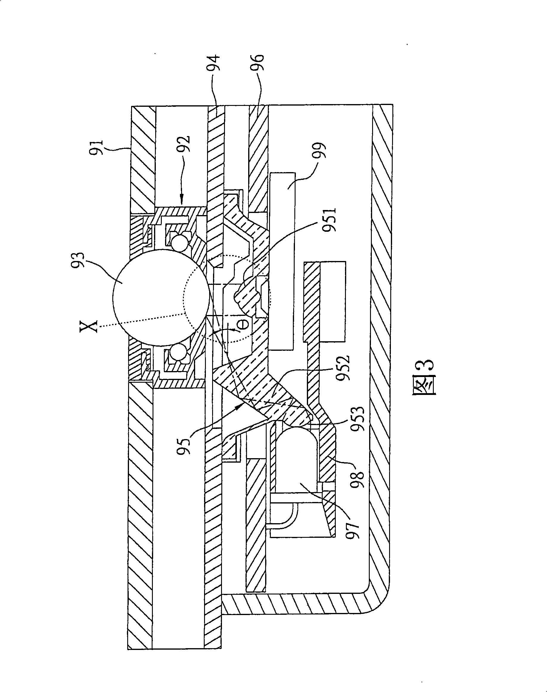
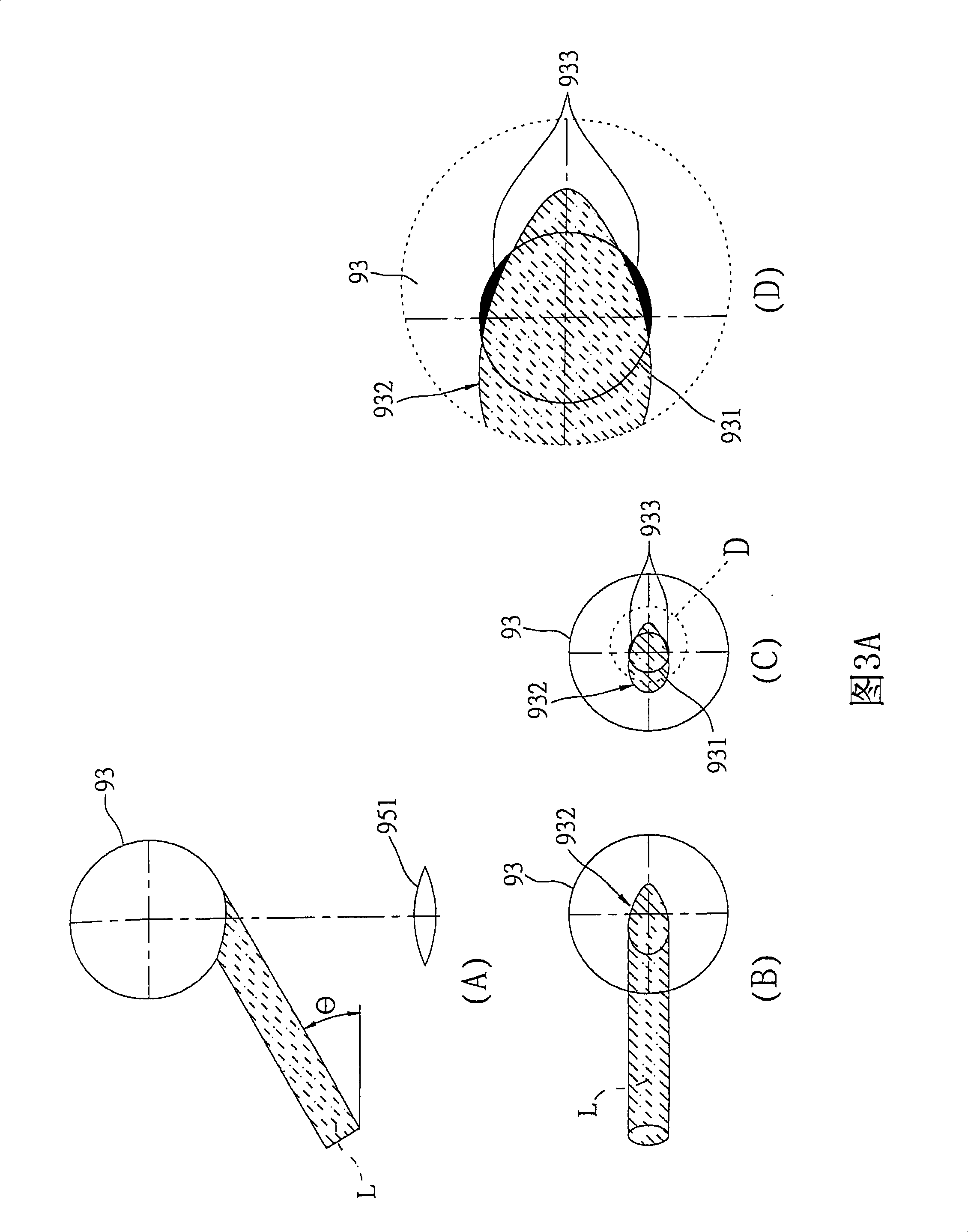
[0010] It is particularly worth mentioning that, as shown in (A) and (B) of FIG. 3B , especially when the angle value of the projection angle θ is larger, the range of the shadow area 933 will be relatively larger, as shown in FIG. As shown in (C) of 3B, the shaded area 933 has relatively changed / expanded within the scope of the image capture area 931, and it is impossible to capture more complete displacement data; therefore, the overall design of the structure obviously cannot Obtain complete displacement data, so that there are unsatisfactory disadvantages in operation

Method used


Image

  • Optical multipurpose image detecting structure
  • Optical multipurpose image detecting structure
  • Optical multipurpose image detecting structure

Examples


Embodiment Construction

[0068] see Figure 4 to Figure 6 As shown, the present invention provides an optical multi-purpose image detection structure, which includes a housing 10 , a trackball 20 , an optical seat 30 , a circuit board 40 , a light emitting element 50 and an image sensor 60 .

[0069] Wherein, the main function of the casing 10 is to accommodate the trackball 20 , and the casing 10 can have a shell 11 , a seat 12 and a fixed cover 13 . The casing 11 defines an accommodating space 111 from top to bottom, and two opposite holes 112 are defined on the side edge. There is a through hole 121 at the center of the seat 12, and several rotatable balls 122 are installed in the interior, and the seat 12 is provided with several gaps 123 so that part of the bead surface of each ball 122 is exposed outside the seat 12 . A through hole 131 is defined in the fixed cover 13 .

[0070] The optical base 30 is provided with a beam splitter 31 arranged obliquely, and a lens element 32 integrally arran...


PUM


Abstract

The invention relates to an optical multipurpose image detection structure which comprises a casing, a trackball, an optical support, a circuit board, a photocell and an image sensor. The casing is used for containing the trackball. The optical support is equipped with an inclined spectroscope for facing to part of the spherical surface of the trackball and a lens element which is arranged on one side of the spectroscope. The photocell and the image sensor are electrically connected with the circuit board. The photocell faces to the spectroscope, and the image sensor faces to the lens element. An optical axis of a projected light source produced by the photocell can be projected on the spherical surface of the trackball by one time or more than one time of the reflection / transmission of the spectroscope. The light source can be projected on the spherical surface uniformly to uniformly achieve capturing images. And the image sensor can obtain complete images for the calculation of complete displacement data.

Description

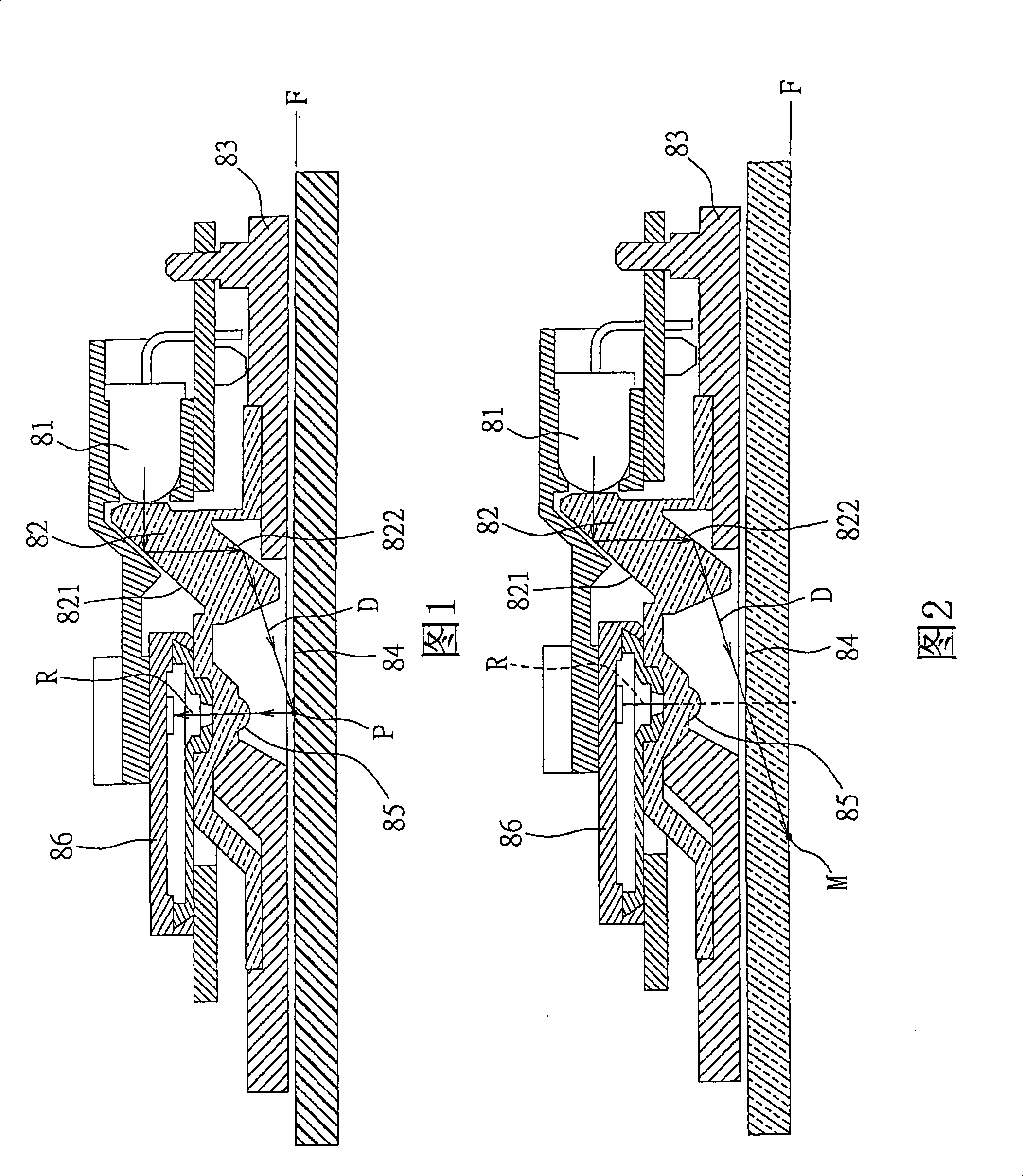
technical field [0001] The present invention relates to an optical multi-purpose image detection structure, in particular to an optical multi-purpose image detection structure that captures the moving distance and direction of a trackball to calculate a displacement data. Background technique [0002] A desktop computer or a notebook computer can be used to control the movement of the cursor on the display through a mouse or a trackball device. In terms of the use surface of the mouse, an optical mouse is commonly used by users. As shown in FIG. When the first reflective surface 821 of the light plate 82 is turned on, the light source will be reflected to the second reflective surface 822, and through the reflection of the second reflective surface 822, the light source will pass through the opening of the bottom case 83 and projected onto a non-transparent interface to form a The contact surface 84, which can overlap with the image axis F, the image of the image axis F is ...

Claims


Application Information

Patent Timeline
Patent Type & Authority Applications(China)
IPC IPC(8): G06F3/033G06F3/0354
Inventor 吕淑芬
Owner PACING TECH
Learn More