Ultra high vacuum magnetron sputtering rectangular plane sputtering target

A magnetron sputtering and ultra-high vacuum technology, which is applied in the field of magnetron sputtering targets, can solve the problems of safe fixation of sputtering targets, poor solderability, affecting the performance and yield of semiconductor devices and circuits, etc., to reduce costs, Overcoming the effect of electrical insulation

Inactive Publication Date: 2008-11-26
HEFEI INSTITUTES OF PHYSICAL SCIENCE - CHINESE ACAD OF SCI
View PDF1 Cites 6 Cited by
  • Summary
  • Abstract
  • Description
  • Claims
  • Application Information

AI Technical Summary

Problems solved by technology

However, there are deficiencies in this sputtering target. First of all, after the magnet seal cover is filled with pure iron, magnets and cooling system, if it is welded and packaged, it will be difficult to carry out necessary maintenance and maintenance of each component in it in the future. Replacement, if it is a cover-type package, air leakage and water seepage will easily occur at the package; secondly, as the cathode, it needs to be electrically insulated from other parts in the sputtering equipment, and the insulating layer is made of non-metallic materials. Just can't use the way of welding to solve mutual sealing problem; Again, because of the defect on structure, the vacuum degree of sputtering equipment can only reach 10-5Pa at the highest, because the vacuum degree...

Method used


Image

  • Ultra high vacuum magnetron sputtering rectangular plane sputtering target
  • Ultra high vacuum magnetron sputtering rectangular plane sputtering target
  • Ultra high vacuum magnetron sputtering rectangular plane sputtering target

Examples


Embodiment Construction

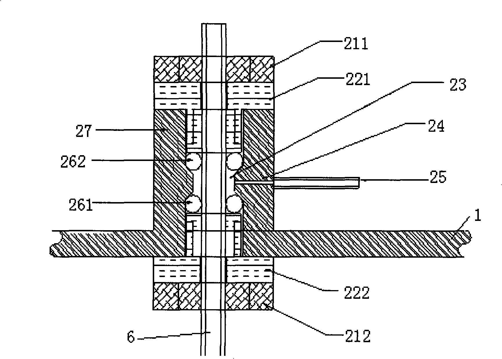
[0014] see figure 1 , figure 2 , image 3 , Figure 4 and Figure 5, the water-cooled cavity part 5 located in the target shield 3 is respectively connected with the cooling water pipe 6 and the support screw 10, and the cooling water pipe 6 and the support screw 10 are respectively connected with the mounting flange 1 through the cooling water pipe sealing part 2 and the supporting screw sealing part 7 connect. The specific connections are as follows: the two end faces of the inner cavity neck of the flange boss 27 of the cooling water pipe sealing part 2 are respectively equipped with O-shaped sealing rings (262, 261) and insulating sleeves which are sleeved on the outside of the cooling water pipe 6. Gaskets (221, 222), wherein the O-shaped sealing rings (261, 262) are O-type fluorine rubber rings, and now it is preferred that the O-shaped fluorine rubber rings be Viton-type fluorine rubber rings. The upper tightening nut 211 and the lower tightening nut 212 are respe...


PUM


Abstract

The invention discloses an ultrahigh vacuum magnetron sputtering rectangular plane sputtering target, which comprises a cooling pipe (6) which runs through a mounting flange (1) and is connected with water-cooling cavity parts (5) in a target shielding cover (3). Especially, (a): the cooling pipe (6) is connected with the mounting flange (1) by a sealing part (2) of the cooling pipe; (b), the water-cooling cavity parts (5) are an upper flange (511) and a lower flange (512) of the water-cooling cavity which are connected with a screw (53) by a sealing ring (52); the lower flange (512) of the water-cooling cavity is internally provided with a soft iron (58) and a permanent magnet (54); the cooling pipe (6) is communicated with the water-cooling cavity parts by welding after running through the bottom of the water-cooling cavity parts; a nut (57) is against and connected with an insulating sleeve gasket (56) sheathed on the outside of the cooling pipe by the external thread of the cooling pipe (6) in a pressing way; (c), the rectangular plane sputtering target further comprises at least one supporting screw (10) and a sealing part (7) of the supporting screw which is connected with the supporting screw in a matching way. The vacuum degree of the ultrahigh vacuum magnetron sputtering rectangular plane sputtering target reaches up to more than 6*10<-6>Pa, which can be used for high-quality coating of work pieces with large surface area.

Description

technical field [0001] The invention relates to a magnetron sputtering target, in particular to an ultra-high vacuum magnetron sputtering rectangular plane sputtering target. Background technique [0002] Magnetron sputtering technology uses the combined action of electric field and magnetic field to make electrons spiral in the narrow space surrounded by the magnetic field lines and the target surface, which improves the collision probability between electrons and sputtering gas atoms, so it has a high sputtering rate. , low voltage, high efficiency and low substrate temperature. Since its inception, the film preparation process has undergone tremendous changes due to its two characteristics of high speed and low substrate temperature rise. At present, magnetron sputtering coating has become one of the most important technologies in industrial coating production. With the continuous expansion of its application field, the surface area of ​​the workpiece to be coated is als...

Claims


Application Information

Patent Timeline
IPC IPC(8): C23C14/35
Inventor 邱凯韩奇峰姬长建曹先存段铖宏尹志军李新化王玉琦
Owner HEFEI INSTITUTES OF PHYSICAL SCIENCE - CHINESE ACAD OF SCI
Why Eureka
Try Eureka