
Service implementing method using incontinuous accepting state

A technology of receiving state and implementation method, applied in the field of communication, can solve the problems of large delay of voice data, inability to effectively guarantee the service quality of various services, without specific consideration of the specific business requirements of real-time business concurrent services, etc. The effect of improving business processing efficiency

Inactive Publication Date: 2008-10-29
江苏普惠银杏产业发展有限公司
View PDF1 Cites 10 Cited by
  • Summary
  • Abstract
  • Description
  • Claims
  • Application Information

AI Technical Summary

Problems solved by technology

[0006] However, the VOIP service is very sensitive to delay requirements, and the maximum tolerant delay is 20ms. If two discontinuous reception states are used for the VOIP service according to the length of voice activation and silence time, then if the above-mentioned long_DRX is used when the UE is in silence state (the discontinuous cycle period it uses is greater than 20ms and less than 160ms), then when the UE is in this state, it is in a sleep state and no longer monitors any physical channel, so if the peer needs to communicate with the UE during this state If you are talking, the data can only be buffered, and the data can only be received when the UE wakes up, which will cause a relatively large delay in the voice data, which cannot meet the quality requirements of the VOIP service
Therefore, this cannot meet the requirements for real-time services that are very sensitive to delay requirements
[0007] However, in the current practice, when using the discontinuous reception technology (specifically, the discontinuous reception state), the specific service requirements of real-time services, non-real-time services, and concurrent services are not specifically considered, so various services cannot be effectively guaranteed. Especially the service quality of real-time business

Method used


Image

  • Service implementing method using incontinuous accepting state
  • Service implementing method using incontinuous accepting state
  • Service implementing method using incontinuous accepting state

Examples


example 1

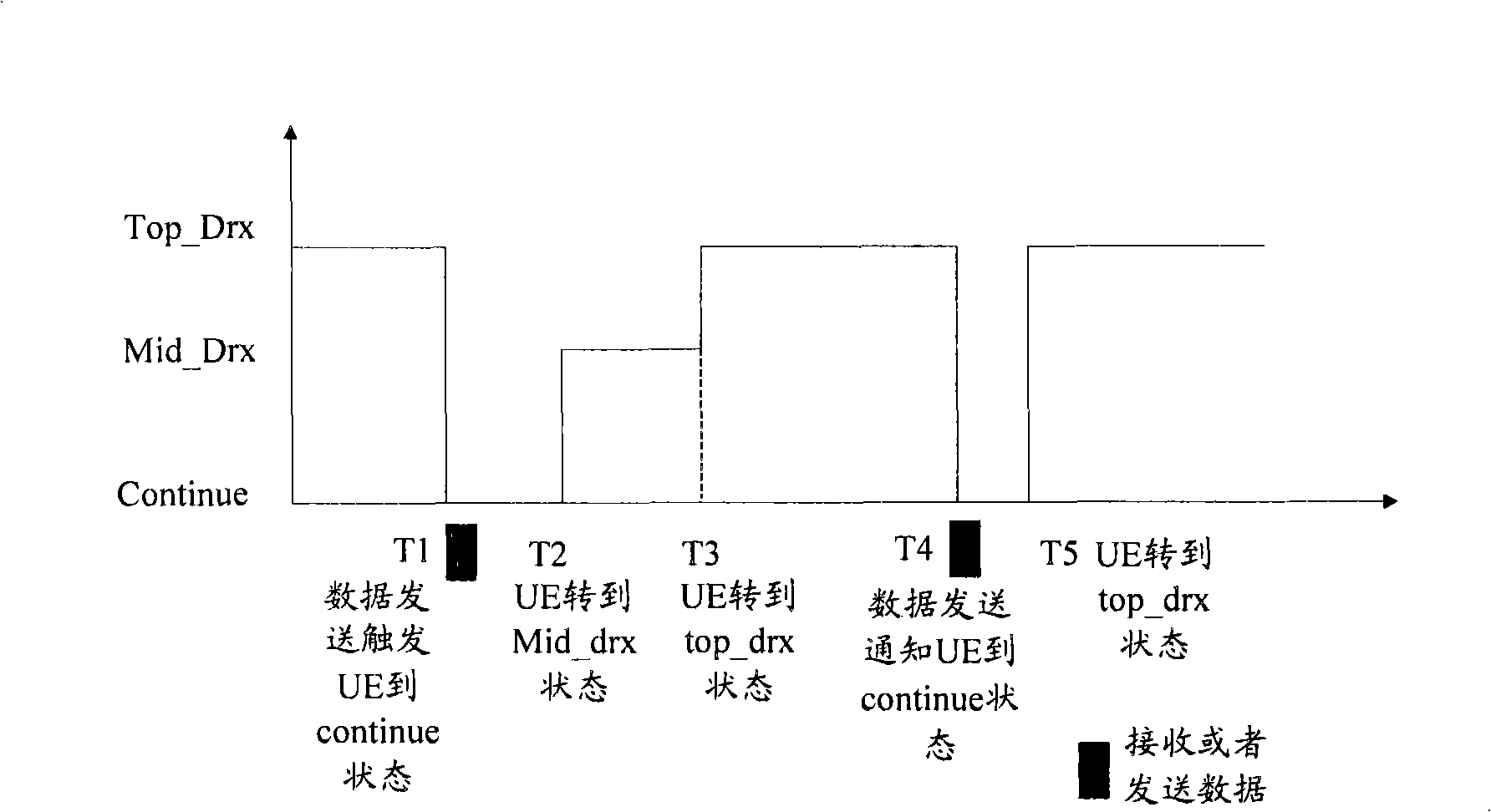
[0040] In this example, the method of using the discontinuous reception state for the VOIP service is specifically described, such as figure 1 Shown:

[0041] Time point T1: UE is in the top_DRX state, and when there is data sent to the UE, the UE enters the continue state;

[0042] Time point T2: when the timer for transferring to top_DRX arrives, the UE transfers to the top_DRX state;

[0043] Time point T3: UE is in top_DRX state, when there is data to send to UE, UE turns to continue state;

[0044] Time point T4: the base station notifies the user equipment to enter the top_DRX state through explicit signaling;

[0045] Time point T5: the UE is in the top_DRX state, and when there is data to be sent to the UE, the UE enters the continue state.

[0046] It can be seen from the above processing that in the technical solution provided by the present invention, real-time services such as VOIP services only use the top_DRX state instead of the mid_DRX state.

example 2

[0048] In this example, the method of using the discontinuous reception state for non-real-time services is specifically described, such as figure 2 Shown:

[0049] Time point T1: UE is in the top_DRX state, and when there is data sent to the UE, the UE enters the continue state;

[0050] Time point T2: when the timer for transitioning to mid_DRX arrives, the UE transitions to the mid_DRX state;

[0051] Time point T3: when the timer for transferring to top_DRX arrives, the UE transfers to the top_DRX state;

[0052] Time point T4: UE is in the top_DRX state, and when there is data sent to the UE, the UE enters the continue state;

[0053] Time point T5: the base station notifies the UE to enter the top_DRX state through explicit signaling.

[0054] It can be seen from the above processing that in the technical solution provided by the present invention, non-real-time services can use the top_DRX state and mid_DRX state.

[0055] It should be noted that there may be multi...

example 3

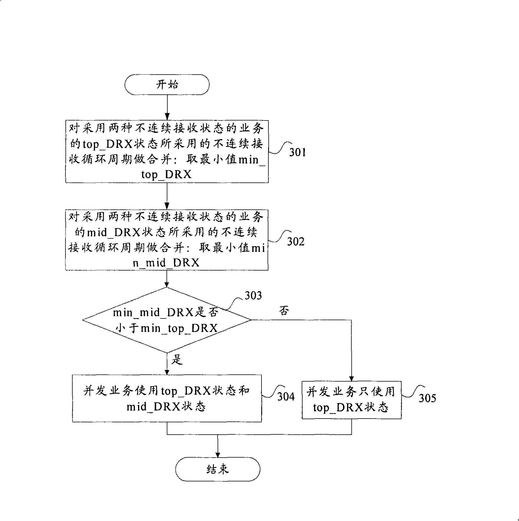
[0066] image 3 shows a specific processing example in this case, such as image 3 shown, including the following steps:

[0067] Step S301, merging the discontinuous reception cycle period adopted by the top_DRX state of the service (ie, non-real-time service) using two discontinuous reception states: take the minimum value min_top_DRX;

[0068] Step S302, merging the discontinuous reception cycles adopted by the mid_DRX state of the services (that is, non-real-time services) using two discontinuous reception states: taking the minimum value min_mid_DRX;

[0069] Step S303, if min_mid_DRX is less than min_top_DRX, execute S304; otherwise execute S305;

[0070] Step S304, the concurrent service uses top_DRX state and mid_DRX state;

[0071] In step S305, the concurrent service only uses the top_DRX state.

[0072] Case 3: Concurrent services are a combination of real-time services and non-real-time services

[0073] In this case, for concurrent services, the method furthe...


PUM


Abstract

The invention relates to a service fulfillment method for using discontinuous receiving status. The method comprises the following steps: the discontinuous receiving status, which is controlled by a longest discontinuous receiving circulation cycle of a plurality of discontinuous receiving circulation cycles which are configured for a terminal, is set as the highest discontinuous receiving status; the discontinuous receiving status, which is controlled by other discontinuous receiving circulation cycles of the discontinuous receiving circulation cycles that are smaller than the longest discontinuous receiving circulation cycle, is set as the intermediate discontinuous receiving status; and regarding to concurrent services, the discontinuous receiving status used by the concurrent servicesis determined according to the discontinuous receiving status used by the real time services and / or non-real time services, wherein, the discontinuous receiving status comprises the highest discontinuous receiving status and the intermediate discontinuous receiving status.

Description

technical field [0001] The present invention relates to the communication field, and more particularly, relates to a service realization method using a discontinuous reception state related to a discontinuous reception technology used in a wireless communication system. Background technique [0002] With the further evolution of wireless communication technology, in order to simplify the maintenance state of a user equipment and network side equipment for a user, various states in the radio resource control (Radio Resource Control, referred to as RRC) connection mode are reduced, that is, there are only RRC connected mode and idle mode. In the RRC connection mode, the user equipment can perform data transmission and reception and various measurements. In addition, if the user equipment is in the RRC connection mode, it must always monitor the downlink control channel, which consumes a lot of power for the user equipment. Therefore, The 3GPP (Third Generation Partnership Pro...

Claims


Application Information

Patent Timeline
IPC IPC(8): H04Q7/38H04Q7/32
CPCY02D30/70
Inventor 柯雅珠杜忠达
Owner 江苏普惠银杏产业发展有限公司
Learn More