
Overhang spindle bumper absorber for airliner undercart

A technology for large passenger aircraft and landing gear, which is applied to gas-liquid shock absorbers, chassis, etc., can solve the problems of passengers feeling uncomfortable, affecting the strength of landing gear, and discontinuous reaction force, and achieves simplified setting of inflatable holes, convenient and easy inflation. Operation, the effect of avoiding interference

Inactive Publication Date: 2008-10-29
BEIHANG UNIV
View PDF0 Cites 19 Cited by
  • Summary
  • Abstract
  • Description
  • Claims
  • Application Information

AI Technical Summary

Problems solved by technology

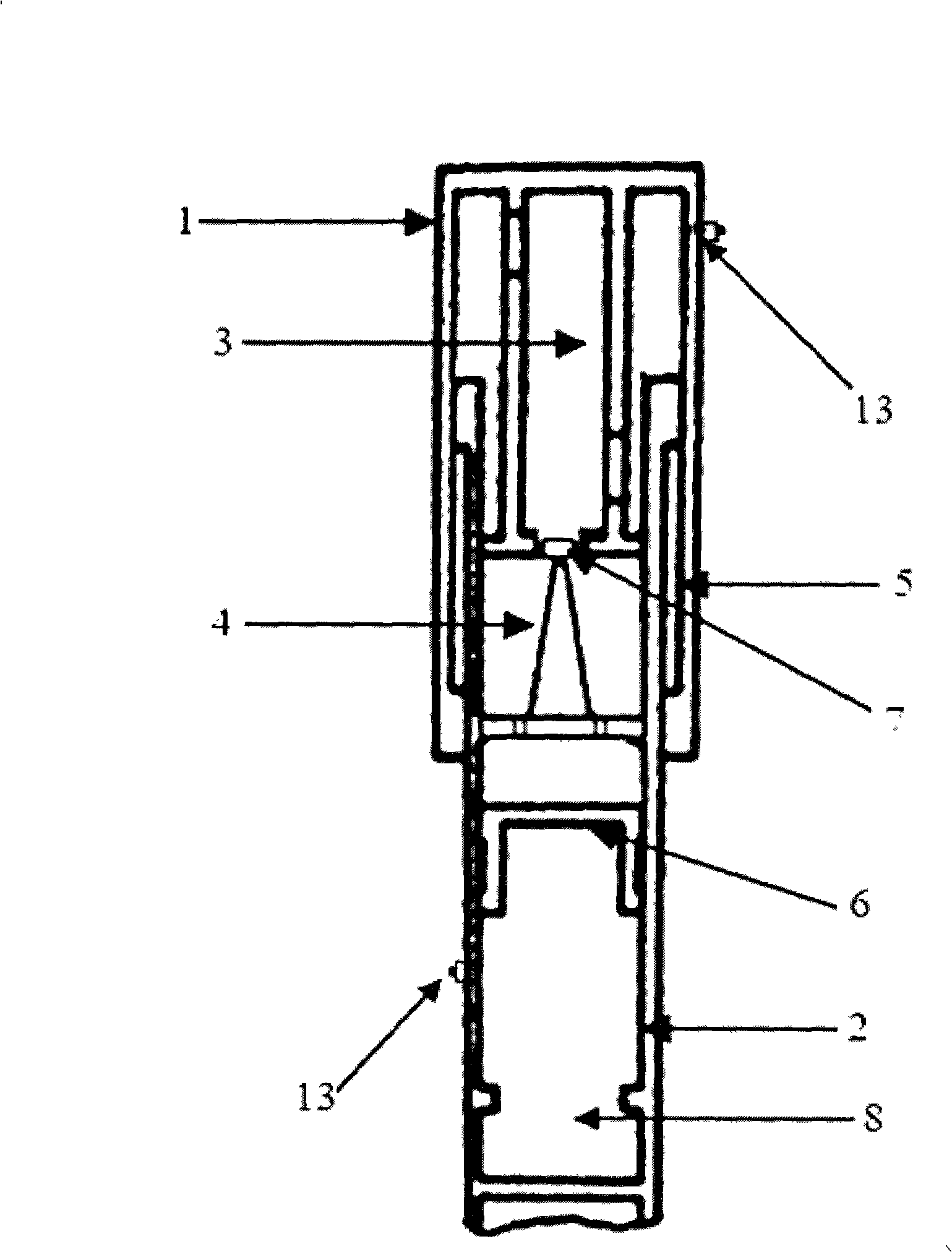
This conventional dual-chamber oil-air buffer is located at the upper end and the lower end of the buffer respectively because the compression damping chamber 3 and the second air chamber 8 are located at the upper end and the lower end of the buffer, that is, in the upper actuator cylinder 1 and the lower actuator cylinder 2. Two air intake valves are required to inflate the chamber, so two air-filling holes 13 will be processed on the outer wall of the buffer, which will cause stress concentration to a certain extent and affect the strength of the landing gear, and the strength of the landing gear is very important for the safety of the entire aircraft. is crucial
The other two air chambers are located at the upper and lower ends of the buffer. At the moment when the landing gear lands, the reaction force generated when the buffer is subjected to external pressure is discontinuous, making passengers feel uncomfortable when riding.

Method used


Image

  • Overhang spindle bumper absorber for airliner undercart
  • Overhang spindle bumper absorber for airliner undercart
  • Overhang spindle bumper absorber for airliner undercart

Examples


Embodiment Construction

[0017] The present invention will be further described in detail below in conjunction with the accompanying drawings.

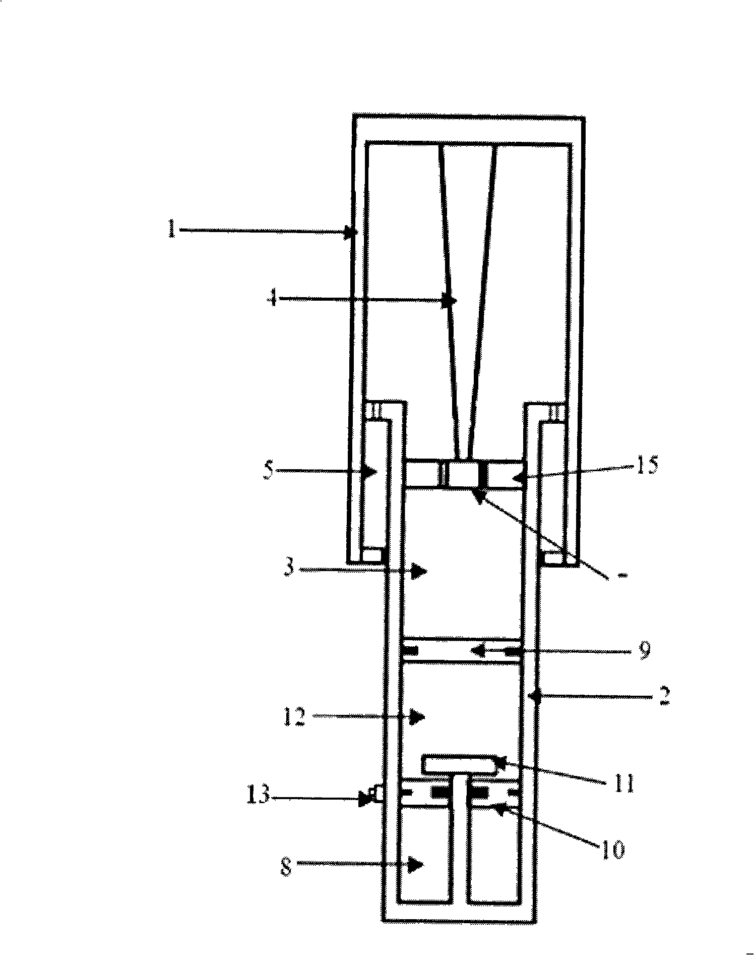
[0018] The present invention resets the placement positions of the traditional buffer air chamber and the oil needle. Such as figure 2 As shown, when the buffer is subjected to external pressure, the low-pressure air chamber 12 is first compressed, and the pressure of the low-pressure air chamber 12 increases thereupon. When the pressure increases to the same pressure as the high-pressure air chamber 8, the high-pressure air chamber 8 starts When the two air chambers are compressed, the oil and gas are pressed into the damping hole 7. Since the oil needle 4 adopts a variable diameter design, the oil needle 4 can change the area of ​​the damping hole 7 at all times when the buffer is compressed.

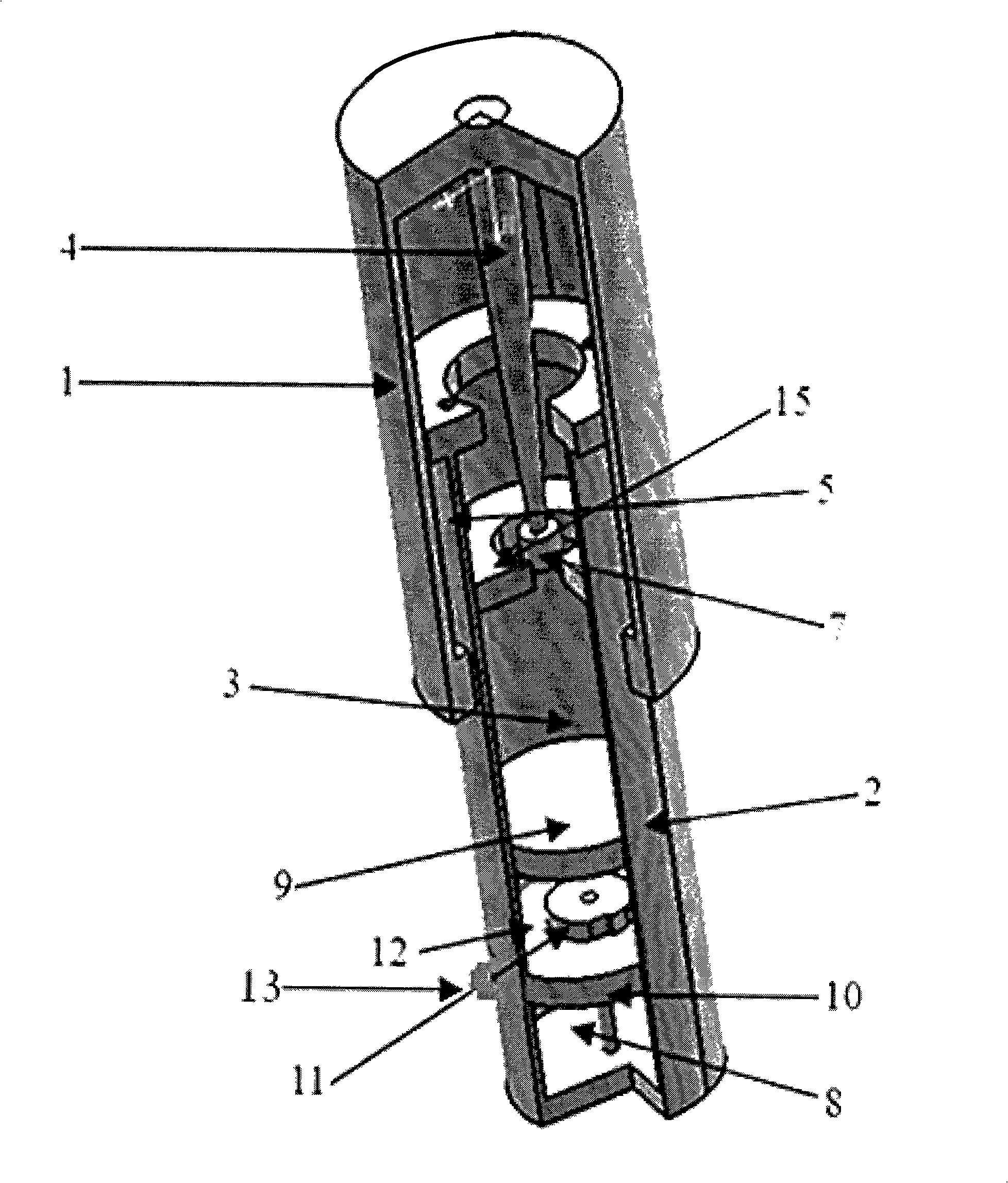
[0019] The main structure of the buffer of the present invention is as image 3 As shown, the high-pressure and low-pressure two air chambers 8, 12 are arranged a...


PUM


Abstract

The invention discloses an overhanging oil needle bumper used for a large aerobus landing gear. The main structure of the overhanging oil needle bumper comprises an upper actuation cylinder, a lower actuation cylinder, a low pressure air chamber, a high pressure air chamber, a compression damping chamber, an oil needle, a damping platform, a damping hole and an inflation hole; the top end of the upper actuation cylinder is connected with the oil needle by screw thread, namely, the oil needle overhangs in the upper actuation cylinder; the internal bottom of the lower actuation cylinder is provided with the low pressure air chamber and the high pressure air chamber which are separated from each other by a movable piston; the lower part of the lower actuation cylinder is provided with the inflation hole, by which two inflation pipelines are led out and respectively connected with the high pressure air chamber and the lower pressure air chamber; the two pipelines are internally provided with two check valves respectively, so as to control the inflation operation. The overhanging oil needle bumper can simplify the arrangement of the inflation hole and lead the inflation to the high pressure air chamber and the lower pressure air chamber to be more convenient. As the dual air chambers are arranged at the lower part of the bumper at the same time, the reaction force generated by the bumper has progressive characteristic when the bumper bears the environmental pressure. Furthermore, the overhanging oil needle bumper has faster pressure transmission and more remarkable damping effect compared with the traditional dual air chamber structures.

Description

technical field [0001] The invention belongs to the technical field of aviation machinery, and in particular relates to a landing gear buffer device of a large civil passenger aircraft. Background technique [0002] Simple holes may often be used as damping holes on small aircraft, this design can give 85% efficiency, as the size of the aircraft increases, especially large passenger aircraft, a variable damping hole is usually required. When the shock absorber starts to compress, the damping speed is slow, so the orifice needs to be smaller to increase efficiency. As the resting position is approached, the damping velocity increases and the orifice needs to be further reduced as the damping velocity approaches zero. [0003] At present, oil needles are often used to change the oil speed on the transport buffers of large passenger aircraft, because this method is simpler, more reliable, does not require maintenance, and is not as complicated as hydraulic valves, and only nee...

Claims


Application Information

Patent Timeline
IPC IPC(8): B64C25/04F16F9/06
Inventor 崔少杰武艺刘沛清李成功田云
Owner BEIHANG UNIV
Learn More