
Controller with pulling resistant structure

A controller and anti-pull technology, which is applied to the parts, electrical components, coupling devices, etc. of the connecting device, which can solve the problems of occupying space, less than ideal structure, and troublesome.

Inactive Publication Date: 2008-10-22
HIWIN MIKROSYST
View PDF0 Cites 1 Cited by
  • Summary
  • Abstract
  • Description
  • Claims
  • Application Information

AI Technical Summary

Problems solved by technology

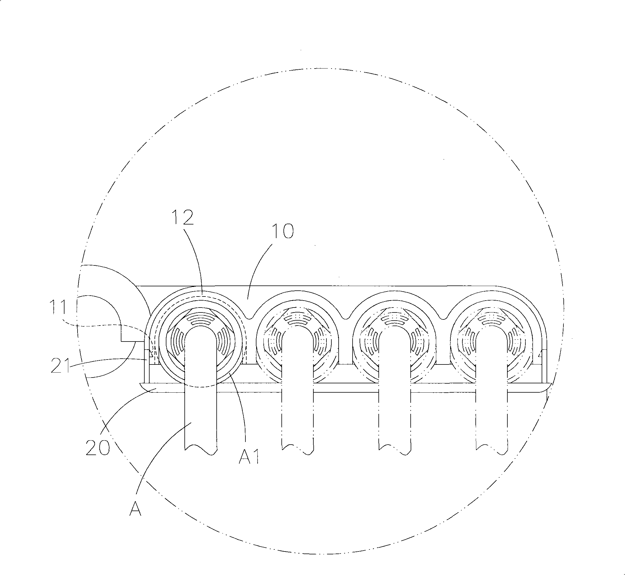
[0005] However, the pull-out prevention structure is positioned by the draw-in groove 11 of the upper block 10 in conjunction with the hook 21 of the lower block 20, which is not so easy and convenient to disassemble, and it is easy to cause the lower block after multiple disassembly. The deformation of the stopper 20 will seriously cause the fracture of the lower stopper 20, so this structure is not ideal, and there is still room for improvement
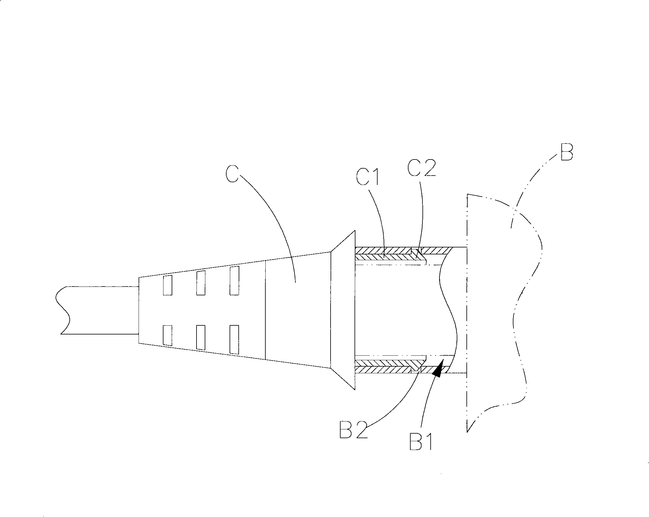
[0006] And another pull-out prevention structure such as figure 2 As shown, two clamping columns C1 are formed on the joint C to match the direction of inserting into the socket B1 of the controller B. The two clamping columns C1 have a hook C2 respectively, and the socket B1 matches the two clamping columns C1. The hook C2 of a clamping column C1 forms two through holes B2, when the joint C is inserted into the socket B1, the joint C can engage and position the hooks C2 of the two clamping columns C1 in the insertion hole B1 respectively. In the two through-holes B2 of the hole B1, the connector C cannot be pulled out from the socket B1 of the controller B;
[0007] However, this kind of pull-out prevention structure must use a specific connector C and controller B. General connectors cannot be used universally. Moreover, the positioning of the hook C2 on the two clamping columns C1 of the connector C must be released first before the connector can be removed. It is quite troublesome to pull out the joint C, and the jack B1 of the controller B is provided with the two through holes B2 for the positioning of the hooks C2 of the two clamping posts C1, and the jack B1 is bound to protrude outward As for the controller B, it takes up space and is not very beautiful, and compared with the previous anti-tear structure, it is even more problematic

Method used


Image

  • Controller with pulling resistant structure
  • Controller with pulling resistant structure
  • Controller with pulling resistant structure

Examples


Embodiment Construction

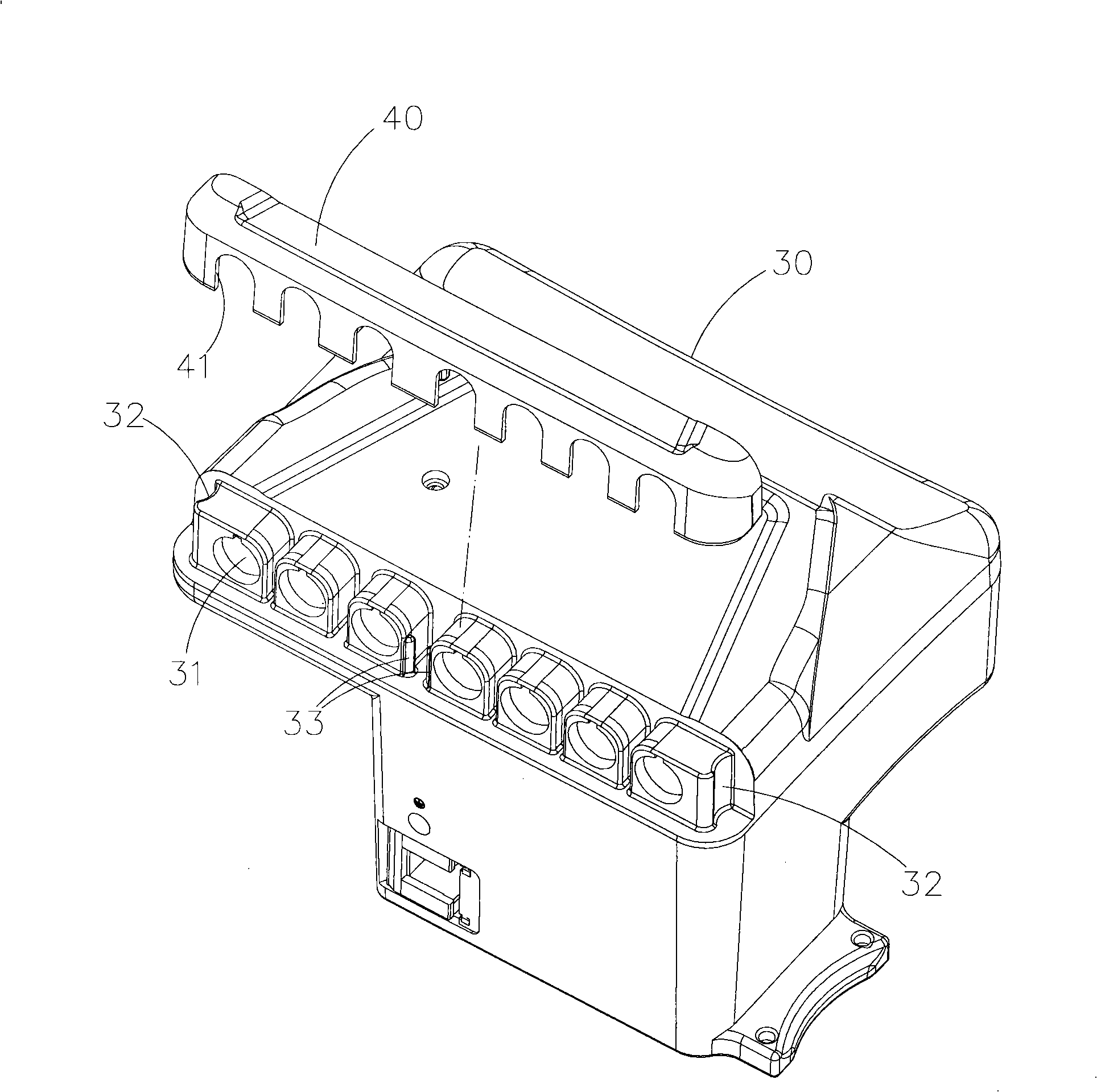
[0034] The controller of the present invention has an anti-pull structure, for example Figure 3 to Figure 7 As shown, the pull-out prevention structure is assembled in the embodiment of the controller such as image 3 and Figure 4 shown, where:

[0035] The controller 30 has a plurality of jacks 31 and joints S detachably inserted into the jacks 31. In this embodiment, the controller 30 forms a positioning recess 32 at its two ends, and each positioning The concave direction of the concave 32 is perpendicular to the insertion direction of the jack, and two convex parts 33 with opposite protrusion directions are formed on the controller 30, and the protrusion direction of each protrusion is perpendicular to the insertion direction of the jack. ;as well as

[0036] The anti-extraction structure 40 is assembled on the controller 30 corresponding to the jack 31 of the controller 30, and the anti-extraction structure 40 forms cutouts 41 corresponding to the number and shape of...


PUM


Abstract

The invention discloses a controller with an anti-drawing structure. A jack and a joint are arranged on the controller; the anti-drawing structure has a notch corresponding to the jack of the controller; the notch is used for limiting the joint in the jack of the controller. The controller not only can prevent the joint form falling out, but also can prevent the joint from being incorrectly inserted in the jack of the controller.

Description

technical field [0001] The invention relates to a controller, in particular to a controller with an anti-pulling structure. Background technique [0002] The controller must be connected with a power cord or a connecting wire and other connectors, so that the power can be supplied by the power cord to start, and the data or signals can be transmitted through the connecting wire to carry out operations. The loss of data, in severe cases, will also cause the stop of the entire system or machine, and the loss is by no means ordinary. [0003] Therefore, there are currently several anti-pulling structures on the market to prevent the connector from falling off the controller socket. Here are two examples, as follows: figure 1 and figure 2 shown, where figure 1 The anti-pulling structure has an upper block 10 and a lower block 20, one end of the upper block 10 is connected with one end of the lower block 20, and the other end has a matching slot 11 and a card slot respectivel...

Claims


Application Information

Patent Timeline
Patent Type & Authority Applications(China)
IPC IPC(8): H01R13/639
Inventor 魏嘉俊林裕健
Owner HIWIN MIKROSYST
Learn More