Modularized coal fines cleaning combustion apparatus
A clean combustion and modular technology, which is applied in the combustion, burner, combustion chamber, etc. using block fuel and powder fuel, can solve the problems of high fuel gas price and low thermal efficiency of operation, and achieves good environmental protection effect and combustion efficiency. High and coal saving effect
Inactive Publication Date: 2008-10-22
赵凯
View PDF0 Cites 11 Cited by
- Summary
- Abstract
- Description
- Claims
- Application Information
AI Technical Summary
Problems solved by technology
Layer-fired furnaces are suitable for burning bituminous coal, and the thermal efficiency of operation is generally low, and fuel gas is expensive
Method used
View moreImage
Smart ImageViewing Examples
Examples
Embodiment Construction
Login to View More PUM
 Abstract
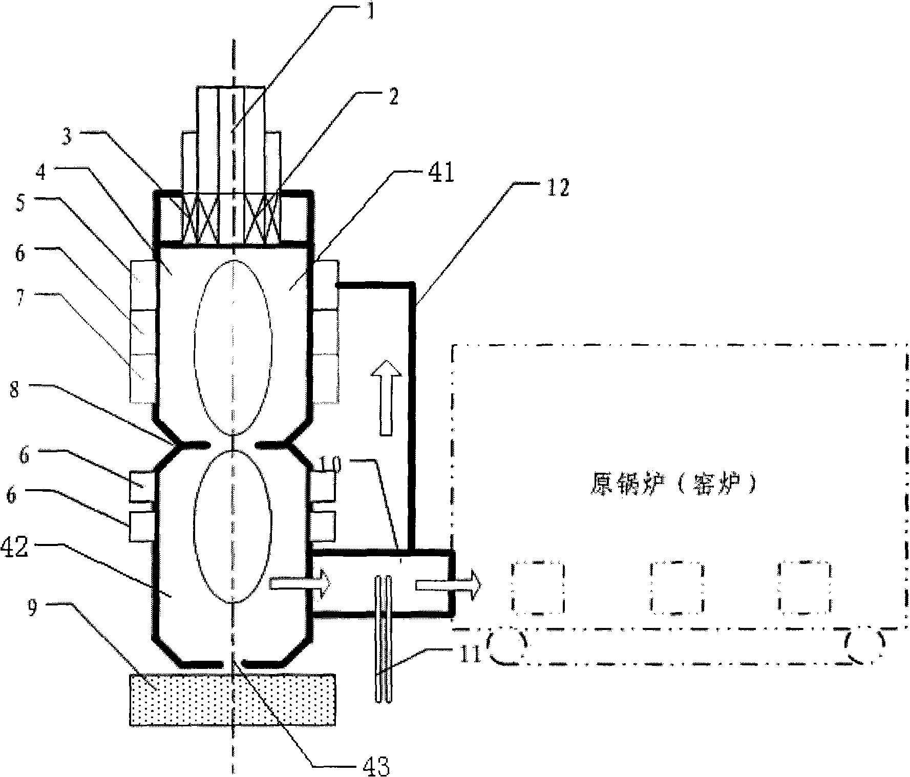
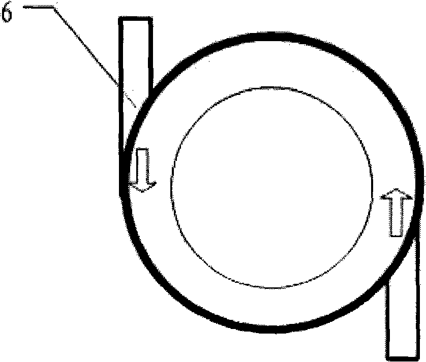
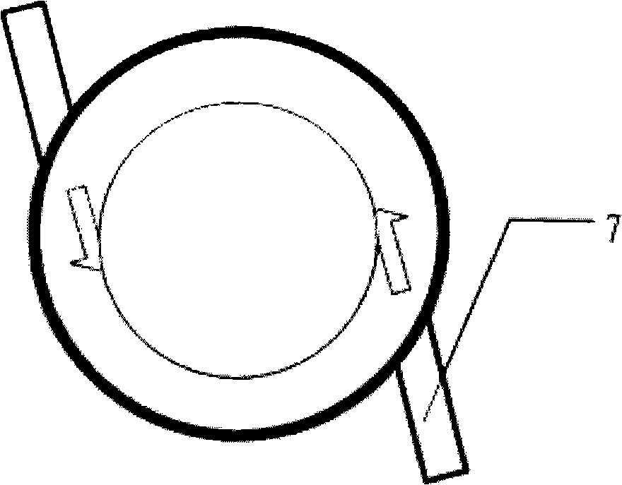
The invention discloses a modularized pulverized coal clean combustion device, relating to a combustion device for a boiler. The modularized pulverized coal clean combustion device comprises a cylindrical burning chamber arranged in the foreside of the boiler; the central part of the upper head face of the burning chamber is provided with a cyclone burner; the middle of the burning chamber is provided with a shrinking waist which divides the burning chamber into an upper burning chamber and a lower burning chamber, wherein the upper burning chamber is connected with a primary wind pulverized coal inlet with direct current incision; the upper and the lower burning chambers are connected with a secondary wind spout with direct current incision; the central part of the bottom of the lower burning chamber is provided with a mouth; a detritus tank is arranged on the corresponding position of the mouth; the tail of the lower burning chamber is connected with the boiler through a burnout chamber. The modularized pulverized coal clean combustion device can be directly in modularized butt joint with a pressed body of the prior boiler, is suitable for burning various pulverized coals, improves thermal efficiency, replaces the prior coal blocks or fuel gas as fuel and has good environment-friendly effect.
Description
Modular pulverized coal clean combustion device technical field The invention relates to a combustion device for a boiler, in particular to a modularized pulverized coal clean combustion device which can be used as a fuel to replace lump coal and fuel gas. Background technique The transformation of small and medium industrial boilers and the replacement of new high-efficiency boilers are the first of the top ten energy-saving projects in the country's "Eleventh and Five-Year Plans". At present, a large number of industrial boilers (kilns) use layer combustion, or burn oil and gas. Layer-fired furnaces are suitable for burning bituminous coal, and their thermal efficiency is generally low, while fuel gas is expensive. With the breakthrough of pulverizing technology, the cost of small-scale production of pulverized coal has been greatly reduced, so that the pulverized coal combustion method can also be applied to small and medium industrial boilers (kilns). Therefore, ch...
Claims
Login to View More Application Information
Patent Timeline
 Patent Type & Authority Applications(China)
IPC IPC(8): F23C3/00F23C6/04F23C5/32F23D1/02F23C9/06
Inventor 赵凯
Owner 赵凯
Features
- R&D
- Intellectual Property
- Life Sciences
- Materials
- Tech Scout
- Unparalleled Data Quality
- Higher Quality Content
- 60% Fewer Hallucinations
Learn More Browse by: Latest US Patents, China's latest patents, Technical Efficacy Thesaurus, Application Domain, Technology Topic, Popular Technical Reports.
© 2025 PatSnap. All rights reserved.Legal|Privacy policy|Modern Slavery Act Transparency Statement|Sitemap|About US| Contact US: help@patsnap.com


