Blocking device vibration device
A technology of vibrating device and block machine, applied in the field of block machine, can solve the problems of increased energy consumption, increased self-weight of synchronizing device, inconvenient eccentric shaft, etc.
Inactive Publication Date: 2008-10-22
李仰水
View PDF1 Cites 5 Cited by
- Summary
- Abstract
- Description
- Claims
- Application Information
AI Technical Summary
Problems solved by technology
When this excitation method is used on a large vibration platform, it is necessary to use multiple sets of eccentric shafts to achieve sufficient excitation force, and the increase in eccentric shafts requires an increase in the number of output shafts of the synchronous vibration device, which will lead to a decrease in the self-weight of the synchronous device. increase, and the weight of the synchronous device needs to be equipped with a more powerful drive motor to generate sufficient excitation force, resulting in increased energy consumption. At the same time, the setting of each eccentric shaft is limited by the diameter of the gear, which becomes very inconvenient
Method used
View moreImage
Smart ImageViewing Examples
Examples
Embodiment Construction
Login to View More PUM
 Abstract
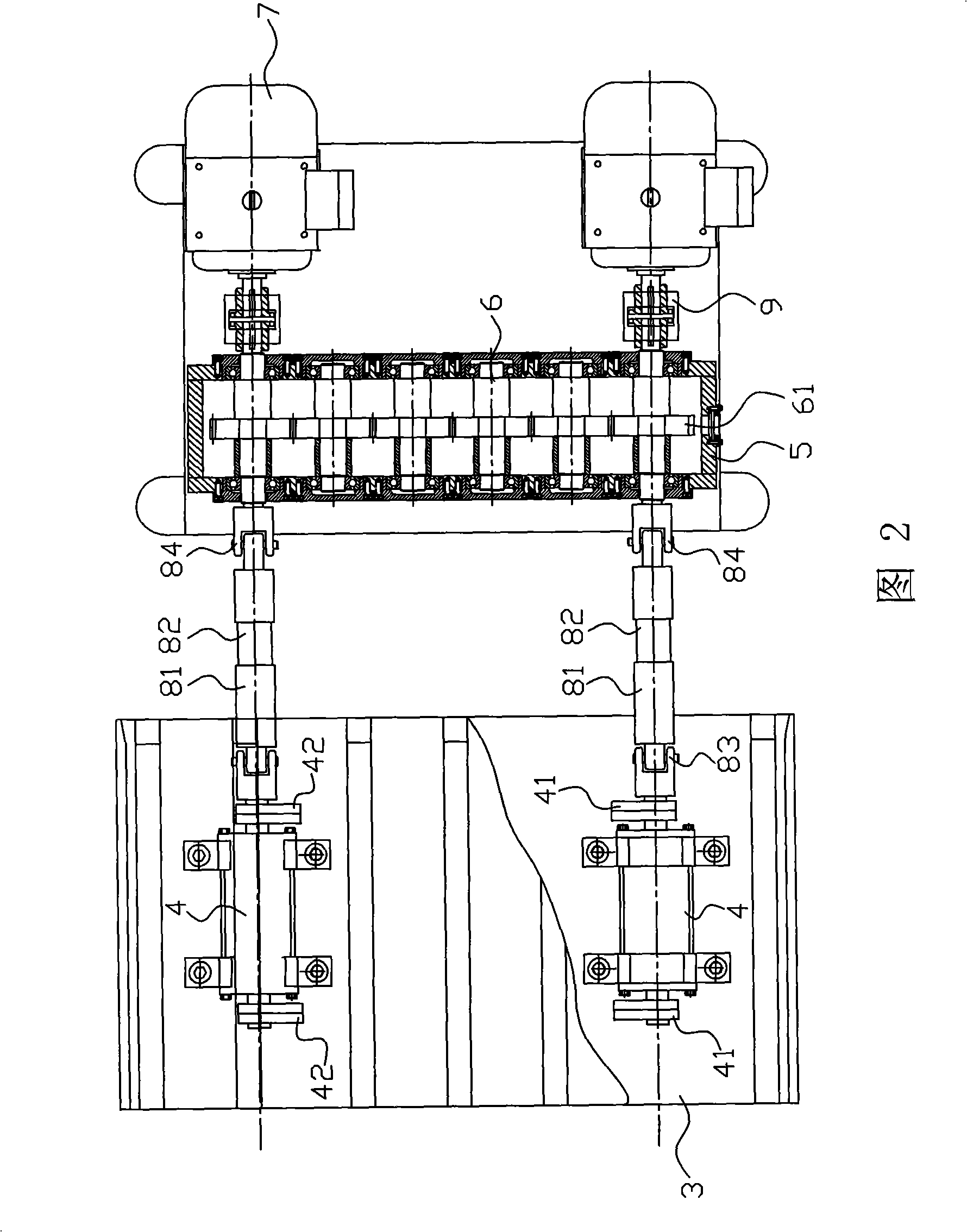
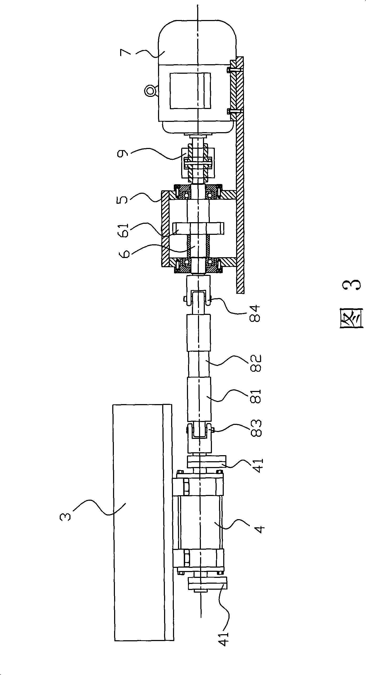
The invention discloses a vibration device for a block machine, which has simple structure and low cost and comprises a synchronous drive device, a vibration platform and a vibration excitation device arranged at the lower part of the vibration platform; the synchronous drive device and the vibration excitation device are connected with each other in a transmission way by a universal connecting device. The synchronous drive device can ensure each vibration excitation of the vibration platform to vibrate synchronously by separating the synchronous drive device from the lower part of the vibration platform and then using the universal connecting device to connect the synchronous drive device and the vibration excitation device in a transmission way; simultaneously, the synchronous drive device is stationary and a power output device only needs to generate enough vibration excitation forces on the vibration platform and vibration generators which are arranged at the lower part of the vibration platform; thereby not only leading the arrangement of each vibration generator to be convenient and flexible, but also being capable of greatly reducing the power of a power device.
Description
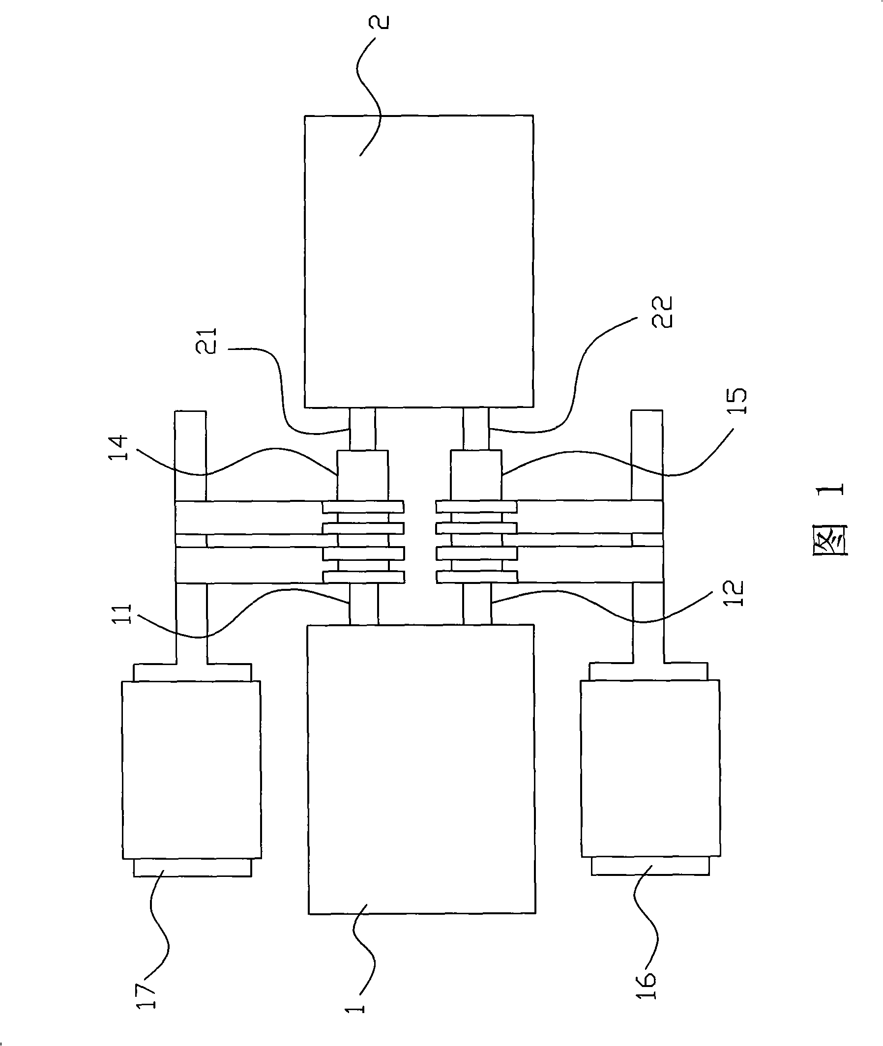
A block machine vibrating device technical field The invention relates to a block machine, in particular to a block machine vibration device. Background technique The application of block machines in industry and agriculture is well known, such as brick machines, coal machines, cement prefabricated panels, etc., and the above-mentioned equipment is generally provided with a vibrating device during the forming process to ensure that the produced blocks have sufficient The compactness and the smallest possible dimensional error, for example, when the bricklaying machine is pressed into the mold box by the indenter, the vibrating motor under the vibrating table is excited to make the material have a fluid-like property and oscillate at high frequency in the mold box so that Fill the space of the mold and achieve a certain degree of compactness to achieve the purpose of improving product quality. With reference to Fig. 1, Chinese patent CN2685046Y announced on March 16, 2005 ...
Claims
Login to View More Application Information
Patent Timeline
 Patent Type & Authority Applications(China)
IPC IPC(8): B28B1/093
Inventor 李仰水
Owner 李仰水
Features
- Generate Ideas
- Intellectual Property
- Life Sciences
- Materials
- Tech Scout
- Unparalleled Data Quality
- Higher Quality Content
- 60% Fewer Hallucinations
Learn More Browse by: Latest US Patents, China's latest patents, Technical Efficacy Thesaurus, Application Domain, Technology Topic, Popular Technical Reports.
© 2025 PatSnap. All rights reserved.Legal|Privacy policy|Modern Slavery Act Transparency Statement|Sitemap|About US| Contact US: help@patsnap.com


