
Machinery room aeration radiation system

A ventilation and heat dissipation technology for computer rooms, applied in the field of heat dissipation systems, can solve the problems of high power consumption and long running time of air conditioners, and achieve the effect of saving power and reducing the frequency of use

Inactive Publication Date: 2008-10-15
汤国江
View PDF0 Cites 3 Cited by
  • Summary
  • Abstract
  • Description
  • Claims
  • Application Information

AI Technical Summary

Problems solved by technology

Although this method can realize the heat dissipation of the computer room of the mobile base station, because the air conditioner is used for forced cooling, the air conditioner runs for a long time and consumes a lot of power

Method used


Image

  • Machinery room aeration radiation system

Examples


Embodiment Construction

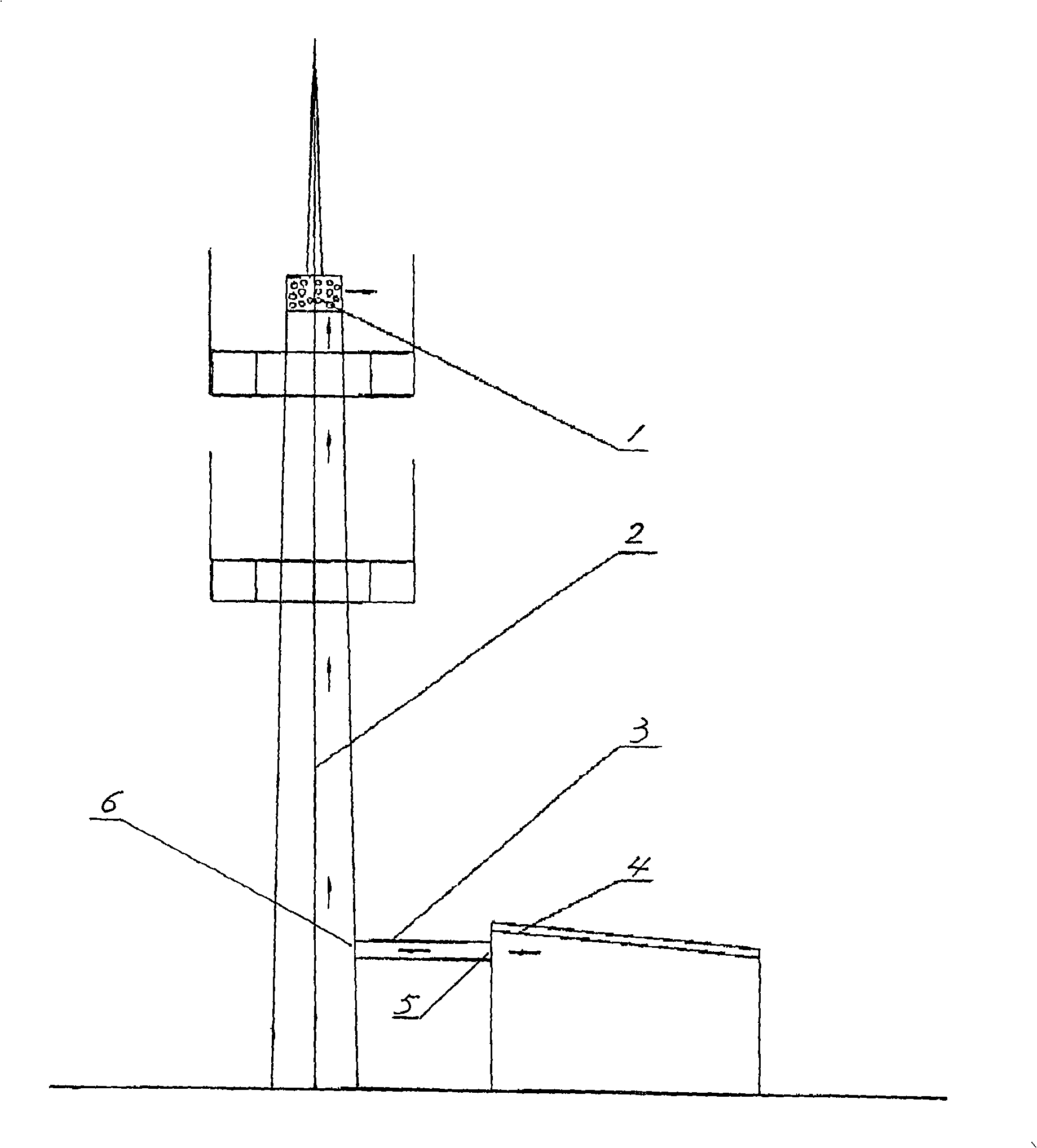
[0009] As shown in the drawings, the machine room ventilation and heat dissipation system of the present invention includes a machine room 4 and a single-pipe tower 2, and the upper and lower walls of the single-pipe tower 2 are respectively processed with an air outlet 1 and an air inlet 6. Wherein there are multiple air outlets 1, and these air outlets are evenly arranged along the upper section of the tower wall of the single-tube tower 2. An air outlet 5 is processed on the wall of the machine room 4 corresponding to the air inlet 6 at the lower part of the single-pipe tower 2, and there is a ventilation duct 3 indirectly between the air inlet 6 and the air outlet 5, so that the air in the machine room 4 passes through the ventilation duct 3 and the single-pipe tower 2 and The outside world is connected. Utilizing the difference in atmospheric pressure caused by the height difference between the upper end of the single-pipe tower 2 and the machine room 4, the hot air in th...


PUM


Abstract

The invention relates to a ventilation and heat dissipation system of an apparatus room, which comprises the apparatus room and a single pipe tower. The invention is characterized in that: an air outlet and an air inlet are respectively arranged on the tower wall on the upper end and the lower end of the single pipe tower; the air outlet is arranged on the wall of the apparatus room corresponding with the air inlet, and a ventilating duct is arranged between the air outlet and the air inlet. The ventilation and heat dissipation system has the advantages of lowering the using frequency of an air -conditioning and saving electricity, and can be applied to the heat dissipation for the apparatus room in mobile base stations.

Description

technical field [0001] The invention relates to a cooling system. Specifically, it is a computer room ventilation and heat dissipation system for cooling the computer room of the mobile base station. Background technique [0002] It is known in the mobile communication industry that the heat dissipation of the computer room of the mobile base station has always been achieved by installing an air conditioner in the computer room and forcing the air in the computer room to cool down. Although this method can realize heat dissipation in the equipment room of the mobile base station, since the air conditioner is used for forced cooling, the air conditioner runs for a long time and consumes a lot of power. Contents of the invention [0003] The problem to be solved by the present invention is to overcome the deficiency of the background technology and provide a ventilation and cooling system for a machine room. Adopting the ventilation and heat dissipation system of the compu...

Claims


Application Information

Patent Timeline
Patent Type & Authority Applications(China)
IPC IPC(8): F24F7/04
Inventor 舒军
Owner 汤国江
Learn More