
High-efficiency full solution type coupled heat exchanger

A flooded heat exchanger technology, which is applied in the field of high-efficiency flooded coupled heat exchangers, can solve the problems of difficulty in improving heat exchange efficiency, increased heat exchanger volume, and low efficiency, achieving improved heat exchange efficiency, The effect of efficient heat exchange

Inactive Publication Date: 2008-10-08
王全龄
View PDF0 Cites 2 Cited by
  • Summary
  • Abstract
  • Description
  • Claims
  • Application Information

AI Technical Summary

Problems solved by technology

Due to the problem of compressor oil return on the evaporation side of the heat exchanger, dry evaporator structures and refrigerant circulation methods are often used, which limits the improvement of its heat exchange efficiency
And because the heat exchange tubes that make up the heat exchanger are generally smooth or rolled with spiral low ribs (the height of the ribs is about 1.5mm), the heat exchange area is small, the ribbing coefficient is low, and the heat exchange efficiency is difficult to improve.
The above reasons directly lead to the increase of the volume of the heat exchanger, low efficiency and high cost

Method used


Image

  • High-efficiency full solution type coupled heat exchanger
  • High-efficiency full solution type coupled heat exchanger
  • High-efficiency full solution type coupled heat exchanger

Examples


Embodiment Construction

[0012] The specific embodiment of the present invention will be described with reference to the accompanying drawings.

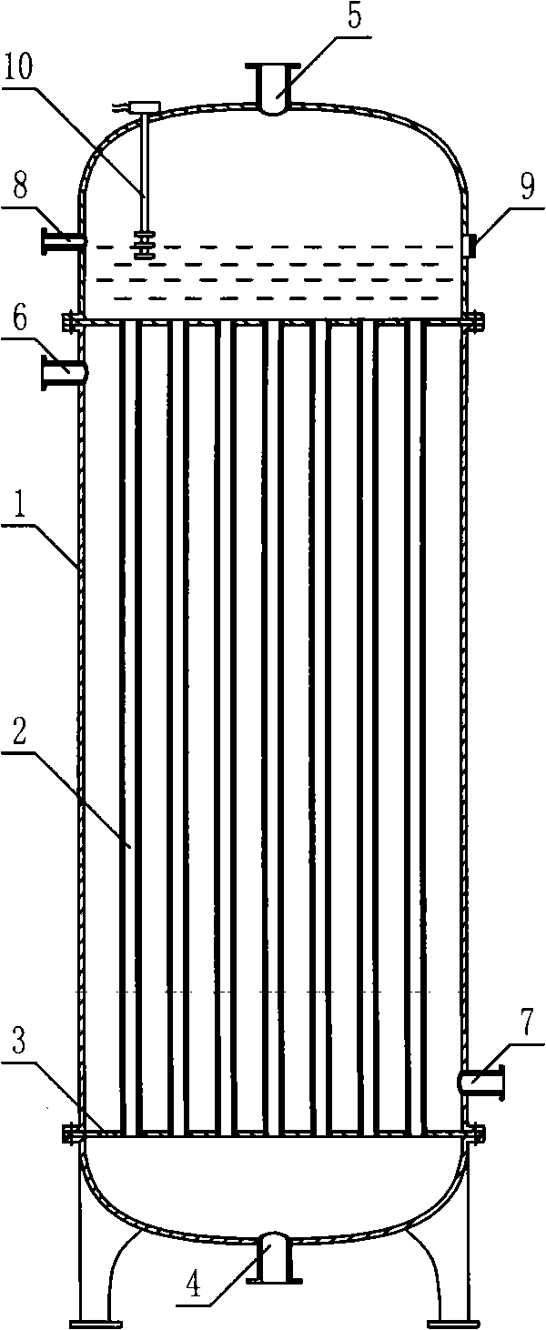
[0013] as attached figure 1 , the heat exchanger has a vertical tank-shaped shell 1, and the upper and lower parts of the shell are respectively provided with heat exchange tubes 2 vertically fixed in the shell and separating the shell into connected via heat exchange tube bundles. The upper and lower tube-side chambers and the upper and lower tube sheets 3 of a shell-side chamber placed in between are connected to the lower tube-side chamber with an evaporating-side refrigerant liquid inlet 4, and connected to the upper tube-side chamber with an evaporating-side refrigerant The gas outlet 5 is provided with a condensation-side refrigerant gas inlet 6 at the upper part of the shell-side chamber, and a condensation-side refrigerant condensate outlet 7 is provided at the lower part of the shell-side chamber, corresponding to the refrigerant liquid level in the...


PUM


Abstract

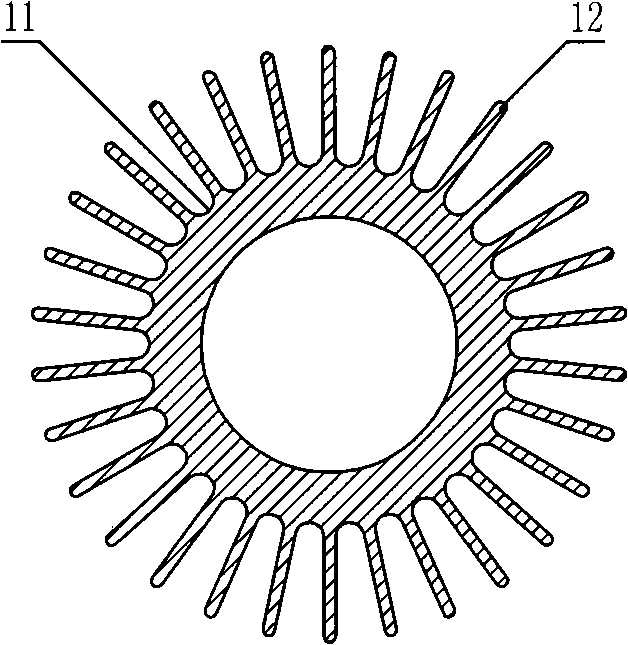
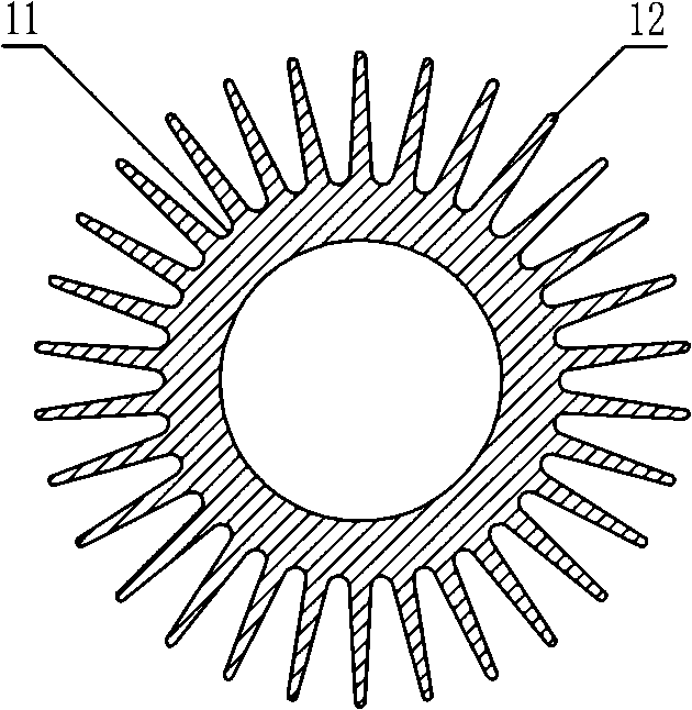
A high efficient liquid filling coupling heat exchanger has a casing. In the casing, a heat exchanging pipe beam is vertically fixed in the casing by a pipe board and divides the casing into an upper and a lower monitor cavity. An evaporate side refrigerating fluid inlet and a gas outlet are arranged corresponding to the monitor cavity. A condensate side refrigerating gas inlet and a condensate liquid outlet are arranged corresponding to the monitor cavity. An oil-return opening, a liquid viewing mirror and a liquid level controller are arranged on the refrigerating fluid level corresponding to the monitor cavity; the heat exchanging pipe is composed of a base pipe and an axially rib that is integrally formed on the base pipe and with a height that is as 0.2 to 0.8 time as an outer diameter of the base pipe; the heat exchanging pipe is provided with an axially inner rib piece that is integrally formed with the base pipe. The invention, because of solving the condenser oil-returning problem of the evaporate side loop, enables the evaporate side to adopt the liquid-filling heat exchanging structure an operation manner and exchanges heat for the heat exchanging pipe by a highly finned coefficient, so as to improve energy efficiency of the heat exchanger.

Description

technical field [0001] The invention relates to heat exchange equipment, in particular to a high-efficiency flooded coupling heat exchanger. Background technique [0002] There are many types of evaporative and condensing heat exchangers at present. Among them, the shell-and-tube heat exchangers are mostly composed of an outer shell and a tube bundle placed in the shell. It is used for heat exchange between two independent circulating working fluids. When the shell-and-tube evaporative-condensing heat exchanger is used for the coupling of two-stage heat pump circuits, the refrigerant in the low-temperature stage heat pump circuit releases heat through the condensation side of the heat exchanger, and the refrigerant in the high-temperature stage heat pump circuit passes through the heat exchanger. The evaporator side absorbs heat to complete the heat exchange between the refrigerants in the two-stage heat pump circuit. Due to the problem of compressor oil return on the evap...

Claims


Application Information

Patent Timeline
Patent Type & Authority Applications(China)
IPC IPC(8): F28D7/10
Inventor 王全龄
Owner 王全龄
Learn More