
Injection moulding method using cold-hot flow passage

A technology of cold runner and hot runner, applied in the field of injection molding, can solve the problems of material waste, waste section length, etc., and achieve the effect of ensuring economy, reducing injection pressure, and ensuring fillability

Active Publication Date: 2008-10-01
SHANGHAI YAHONG MOLDING
View PDF0 Cites 4 Cited by
  • Summary
  • Abstract
  • Description
  • Claims
  • Application Information

AI Technical Summary

Problems solved by technology

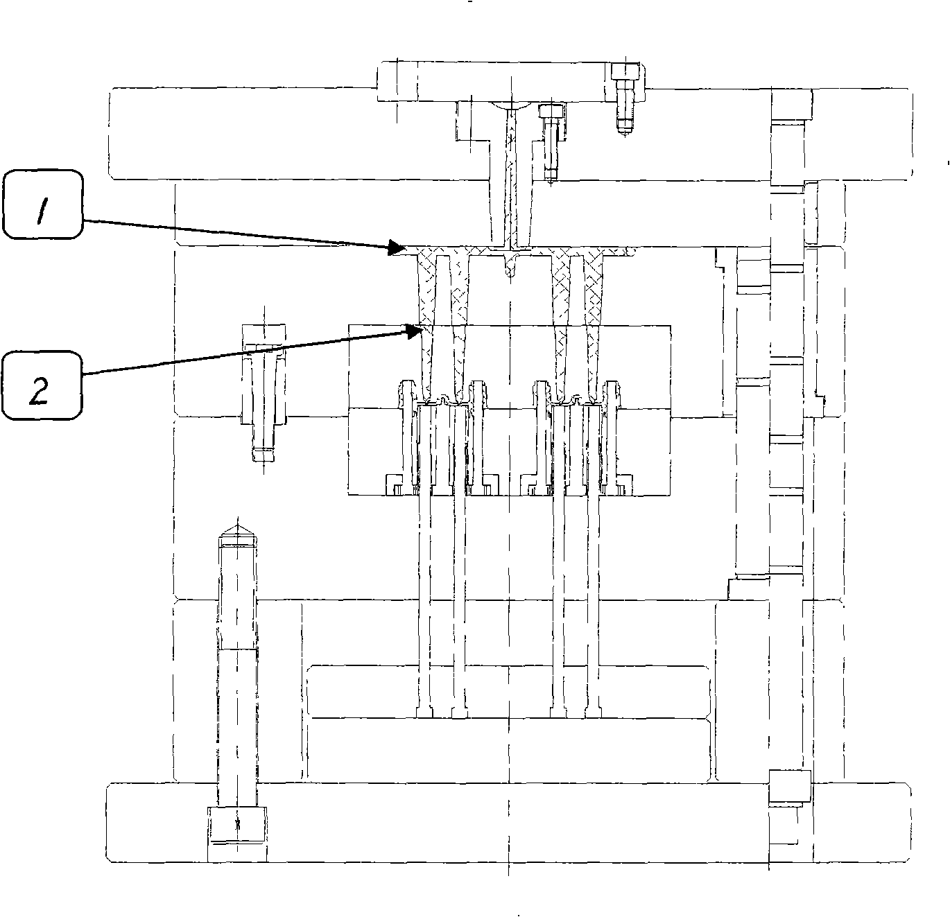
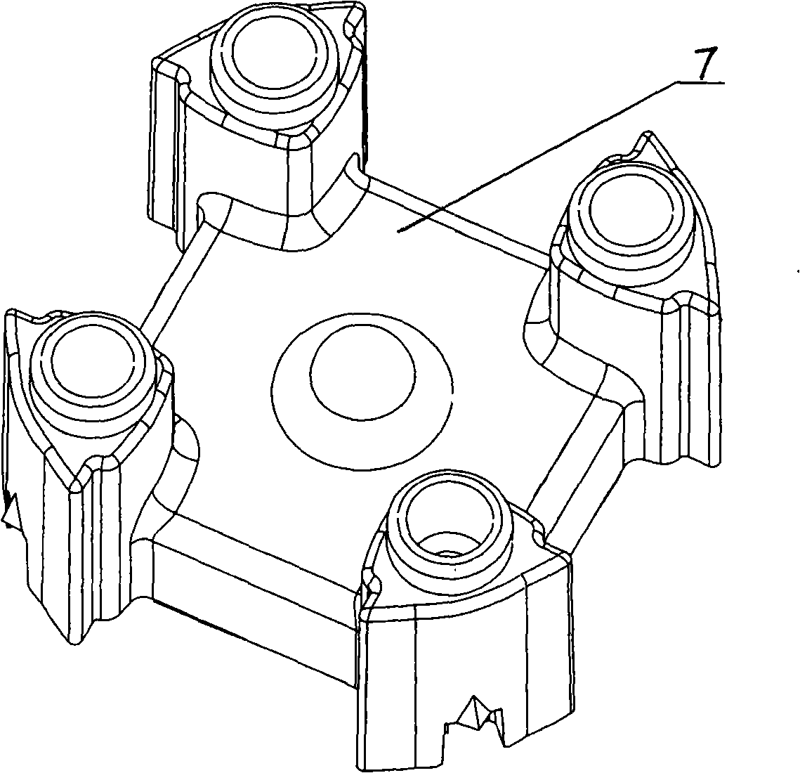
[0002] At present, when using an injection molding machine to inject products, such as figure 1 As shown, the main channel 1 and the sub-runner 2 are used for multi-point cold runner injection, and for such as figure 2 The product wall shown is relatively thick, and the product gate space 7 is smaller than the minimum diameter of the cold runner gate. When the traditional solution is used for multi-point cold runner injection, the waste section produced is very long, resulting in material waste serious

Method used


Image

  • Injection moulding method using cold-hot flow passage
  • Injection moulding method using cold-hot flow passage
  • Injection moulding method using cold-hot flow passage

Examples


Embodiment

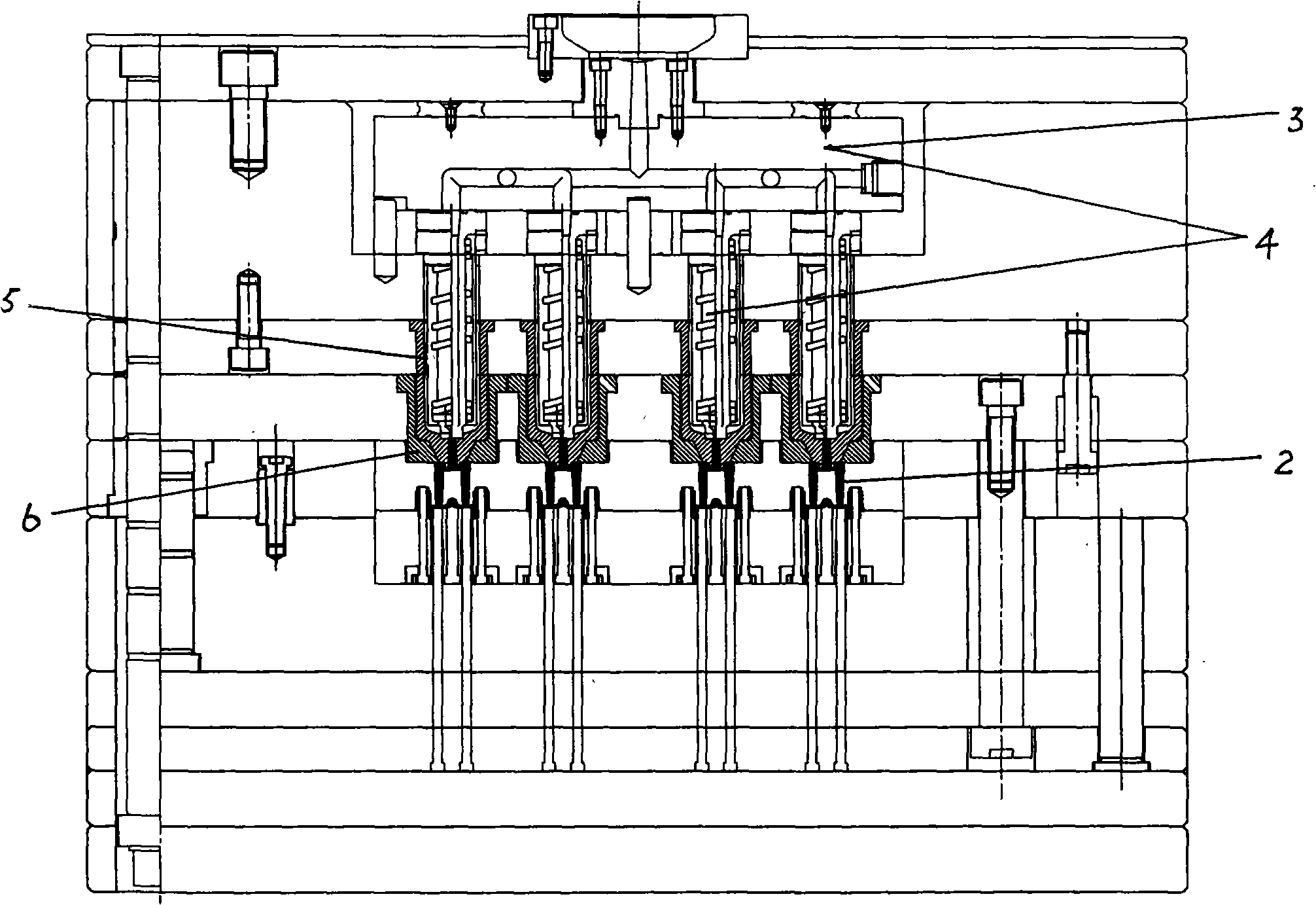
[0016] Such as image 3 Shown is a schematic diagram of the structure of the injection molding runner device of the present invention. The method for injection molding using hot and cold runners is characterized in that the method is:

[0017] In the first step, transition runners 4 are added to the upper ends of the four cold runners 2 of the original injection mold, and runner transition sleeves 5 and degumming sleeves 6 are installed outside the transition runners 4, such as Figure 4 shown;

[0018] In the second step, connect the upper ends of all the transition runners 4 to a hot runner 3 .

[0019] In the present invention, most of the strokes of the main channel 2 and the sub-runner 4 are transferred by the hot runner, that is, the injection molding liquid in the molten state is used for injection molding. The injection molding liquid in the molten state can be heated by electric heating, and the heating temperature is 260°C- 300°C, keep the injection molding liquid ...


PUM


Abstract

The invention relates to a method of injection molding by adopting hot runners and cold runners, which is characterized in that the upper end of each cold runner of a former die for injection molding is additionally provided with a transition runner outside which a transition sleeve and a degumming sleeve are arranged; the upper end of each transition runner is connected with a hot runner containing liquid for injection molding in a molten state; materials for injection molding in the hot runner are heated to 260 to 300 DEG C to ensure that the liquid for injection molding is kept in a molten state; an injection molding machine is then started to cause the molten liquid in the hot runner to be conveyed to the transition runner and then to be separately conveyed to the multipoint cold runner to conduct the multipoint casting so as to complete the injection molding of products. The method of injection molding of the invention has the advantages of controlling sprue wastes in a minimum production amount, ensuring the economic production, reducing the pressure of injection molding and prolonging the service life of the dies.

Description

technical field [0001] The invention relates to a method for injection molding with hot and cold runners, which solves the problem of the injection molding of multi-point glue-injection products whose product inlet space is smaller than the minimum diameter of the hot runner inlet, and belongs to the technical field of injection molding. Background technique [0002] At present, when using an injection molding machine to inject products, such as figure 1 As shown, the main channel 1 and the sub-runner 2 are used for multi-point cold runner injection, and for such as figure 2 The product wall shown is relatively thick, and the product gate space 7 is smaller than the minimum diameter of the cold runner gate. When the traditional solution is used for multi-point cold runner injection, the waste section produced is very long, resulting in material waste serious. Contents of the invention [0003] The object of the present invention is to provide a material-saving injection...

Claims


Application Information

Patent Timeline
Patent Type & Authority Applications(China)
IPC IPC(8): B29C45/00B29C45/26B29C45/73
Inventor 张烨闽
Owner SHANGHAI YAHONG MOLDING
Learn More