Liquid evaporation method and device for implementing the same
A technology of liquid evaporation and generating device, which is applied in the direction of spray evaporation, etc., to achieve the effect of reducing energy consumption and reducing white powder phenomenon
- Summary
- Abstract
- Description
- Claims
- Application Information
AI Technical Summary
Problems solved by technology
Method used
Image

Examples
no. 1 approach
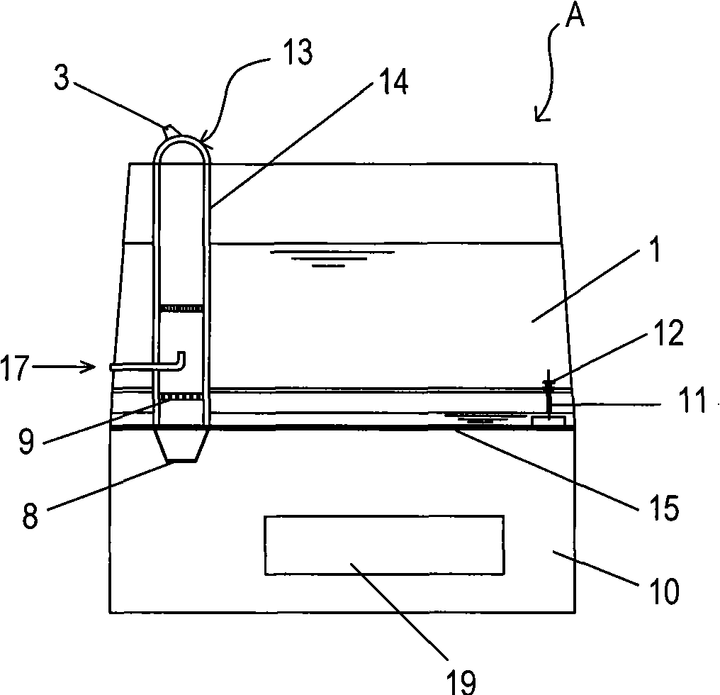
[0028] figure 1 A first embodiment of an apparatus for carrying out the liquid evaporation method of the invention is shown.
[0029] A first embodiment of an apparatus for carrying out the liquid evaporation method of the present invention is a humidifying apparatus A.
[0030] Such as figure 1 As shown, the humidifier A is mainly composed of an upper box 1 and a lower box 10 .
[0031] The upper box body 1 includes a water tank with an opening facing downwards and a steam generating device 13 . The steam generating device 13 has a steam generating housing 14 , and the electric heating body 5 is detachably installed in the steam generating housing 14 , above the ultrasonic generator 8 and the partition 9 . The electric heater 5 is a sheet-like member with a prescribed thickness, its outer contour is adapted to the cross-sectional inner surface of the steam generating housing 14, and has holes or openings for allowing liquid mist, such as liquid mist, to pass therethrough. ...
no. 2 approach
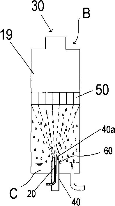
[0045] figure 2 A second embodiment of an apparatus for carrying out the liquid evaporation method of the invention is shown.
[0046] The second embodiment of the device for carrying out the liquid evaporation method of the present invention is a solution concentration device B. Such as figure 2 As shown, this solution concentration device B has, in the sealed housing 1a, the lower part is provided with a liquid ejection mechanism 60 composed of a gas ejection pipe 40 and a liquid supply pipe 20 arranged inside the gas ejection pipe 40. An electric heating body 50 is detachably provided above the liquid ejection mechanism 60 . In addition, in the case 1a, a concentrated liquid storage portion C is defined below the top of the liquid ejection mechanism 60 .
[0047] In addition, the casing 1a is provided with a detachable steam discharge port 30 at the upper part, and a concentrated liquid discharge port 70 is provided at the lower part of the concentrated liquid storage ...
no. 3 approach
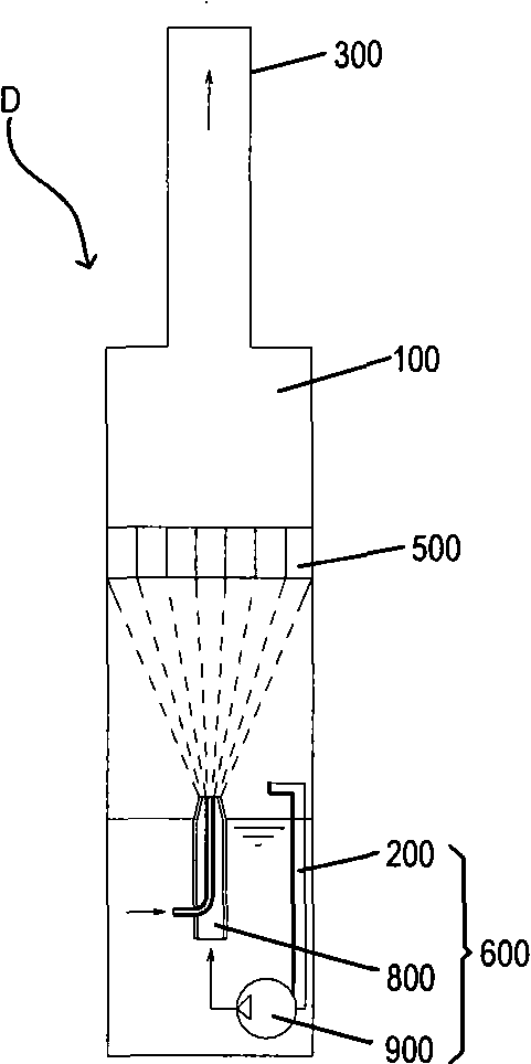
[0059] image 3 A third embodiment of an apparatus for carrying out the liquid evaporation method of the invention is shown.
[0060] The device implementing the liquid evaporation method of the present invention in this embodiment is a steam power device D. The steam power device D has a heating device 500 installed in the casing 100 forming a closed space; steam is obtained from the casing 100, and after the steam is pressurized, it is sprayed into the casing 100 again. The liquid particle ejection device 600 inside.
[0061] Such as image 3As shown, the housing 100 forming the closed space is also provided with a steam outlet 300. As far as the arrangement of the steam outlet 300 is concerned, it can be integrally formed with the housing 100, or it can be separated from the housing 100. The body can be set via screw threads or snap-fitting, or other setting methods. In addition, the casing 100 can withstand higher pressure, such as 10Mpa and the like. In addition, the...
PUM
 Abstract
Description
Claims
Application Information
 - Generate Ideas
- Intellectual Property
- Life Sciences
- Materials
- Tech Scout
- Unparalleled Data Quality
- Higher Quality Content
- 60% Fewer Hallucinations
Browse by: Latest US Patents, China's latest patents, Technical Efficacy Thesaurus, Application Domain, Technology Topic, Popular Technical Reports.
© 2025 PatSnap. All rights reserved.Legal|Privacy policy|Modern Slavery Act Transparency Statement|Sitemap|About US| Contact US: help@patsnap.com