
Relay network over-loading indication reporting method

An overload indication and relay network technology, which is applied in the communication field, can solve the problems of high signaling overhead and frequent triggering of overload indication reports, and achieve the effects of reducing system overhead, improving effectiveness, and refining the network

Inactive Publication Date: 2008-09-24
ZTE CORP
View PDF0 Cites 26 Cited by
  • Summary
  • Abstract
  • Description
  • Claims
  • Application Information

AI Technical Summary

Problems solved by technology

[0011] The present invention is made in consideration of the above problems. Therefore, the main purpose of the present invention is to provide a relay network overload indication reporting scheme to solve the problems of frequent triggering of overload indication reports and large reporting signaling overhead in the related art

Method used


Image

  • Relay network over-loading indication reporting method
  • Relay network over-loading indication reporting method
  • Relay network over-loading indication reporting method

Examples


example 1

[0064] Figure 4 Trigger implementation diagram for BS overload indicator (OI) report, such as Figure 4 As shown, its specific implementation steps are as follows:

[0065] Step 401: the BS determines an area division threshold;

[0066] Step 402: The BS stratifies the network according to the area division threshold;

[0067] Step 403: The BS determines the triggering thresholds of the overload indicator reports of different layers in the network;

[0068] Step 404: The BS determines the triggering threshold of the network overload indicator report;

[0069] Step 405: If the overload indicators in all network layers exceed the trigger threshold, go to step 406, otherwise go to step 408;

[0070] Step 406: BS sets the overload indicator group indication field;

[0071] Step 407, the BS sets the user terminal distinguishing field;

[0072] Step 408, the BS overload indicator is triggered and the field adjustment is completed;

example 2

[0074] Figure 5 Flowchart for triggering of RS overload indicator (OI) reports, such as Figure 5 As shown, the specific implementation steps are as follows:

[0075] Step 501: the RS determines the area division threshold;

[0076] Step 502: RS stratifies the network according to the area division threshold;

[0077] Step 503: The RS determines the triggering thresholds of overload indicator reports in different layers in the network;

[0078] Step 504: The RS determines the triggering threshold of the network overload indicator report;

[0079] Step 505: If the overload indicators in all network layers exceed the trigger threshold, go to step 506, otherwise go to step 514;

[0080] Step 506, the RS sets the overload indicator site type indication field;

[0081] Step 507: RS sets the overload indicator group indication field;

[0082] Step 508, the RS sets the user terminal distinguishing field;

[0083] Step 509, the RS reports an overload indicator report to the BS...


PUM


Abstract

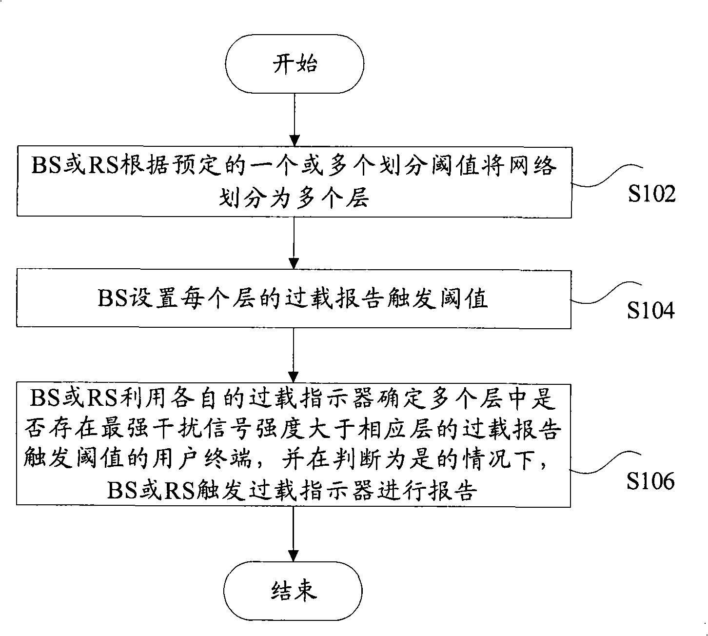
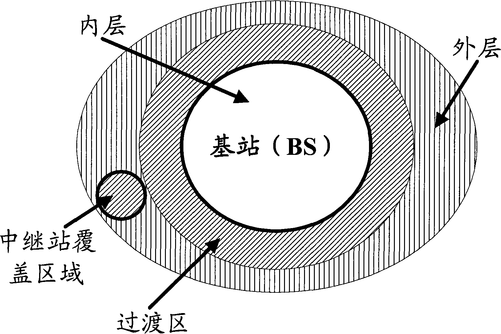
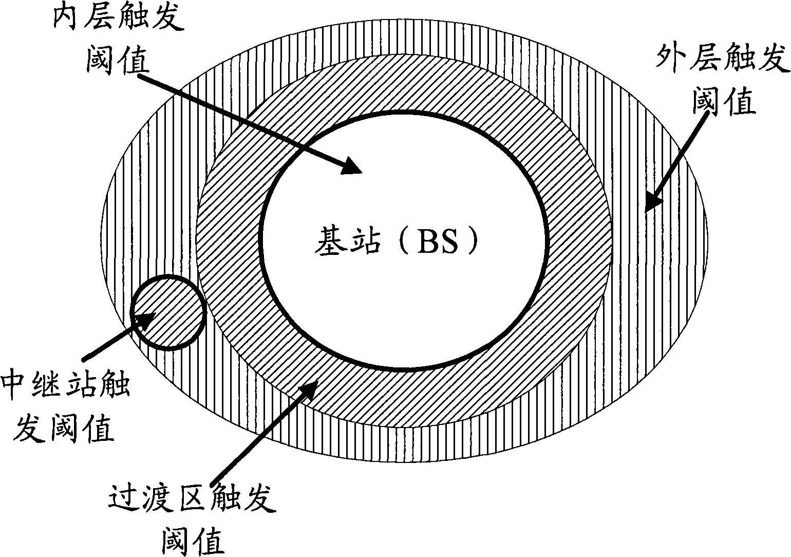
The invention discloses a report method for indicating the overloading of relay network, which includes: a base station or a relay station divides network into a plurality of layers according to one or a plurality of predetermined divided thresholds; the overloading report trigger thresholds are arranged at every layer by the base station; the base station or the relay station makes use of respective overloading indicator to make sure whether a plurality of layers are provided with the user terminals of the overloading report trigger thresholds with the strongest interference signals larger than the corresponding layers. And if yes, the base station or the relay station triggers the overloading indicator to report. With the method of the invention used, the network can be further refined to ensure the overloading indicator to report only the layers which exceed the trigger thresholds. Therefore, the system overhead which is brought by the overloading indicator report is reduced and the efficiency of the overloading indicator is improved.

Description

technical field [0001] The present invention relates to the communication field, and in particular, relates to a relay network overload indication reporting method. Background technique [0002] In the next-generation broadband wireless communication network, especially in the relay network with a relay station (RelayStation, RS), since the RS itself has the characteristics of both a user terminal (UserTerminal, UT) and a base station (Base Station, BS), Therefore, effectively reducing the inter-cell interference in the relay network according to the characteristics of the RS itself is a key factor to effectively improve the inter-cell user terminal (UT) throughput and the average UT throughput, and how to effectively use the relay station is also an important issue at present. serious challenges facing the research institute. [0003] At present, in IEEE 802.16j, IMT-Advanced, and WINNER, solutions such as interference randomization, interference coordination, and interfer...

Claims


Application Information

Patent Timeline
IPC IPC(8): H04Q7/30H04B7/15
Inventor 魏巍支周禹忠
Owner ZTE CORP
Learn More