
Self-adapting echo cancellation method

An echo cancellation and adaptive technology, applied in wired transmission systems, electrical components, transmission systems, etc., can solve the problem of high computational complexity

Inactive Publication Date: 2008-09-24
SUN YAT SEN UNIV
View PDF0 Cites 12 Cited by
  • Summary
  • Abstract
  • Description
  • Claims
  • Application Information

AI Technical Summary

Problems solved by technology

However, the computational complexity of this algorithm is high

Method used


Image

  • Self-adapting echo cancellation method
  • Self-adapting echo cancellation method
  • Self-adapting echo cancellation method

Examples


Embodiment Construction

[0060] The present invention will be further described below in conjunction with the accompanying drawings.

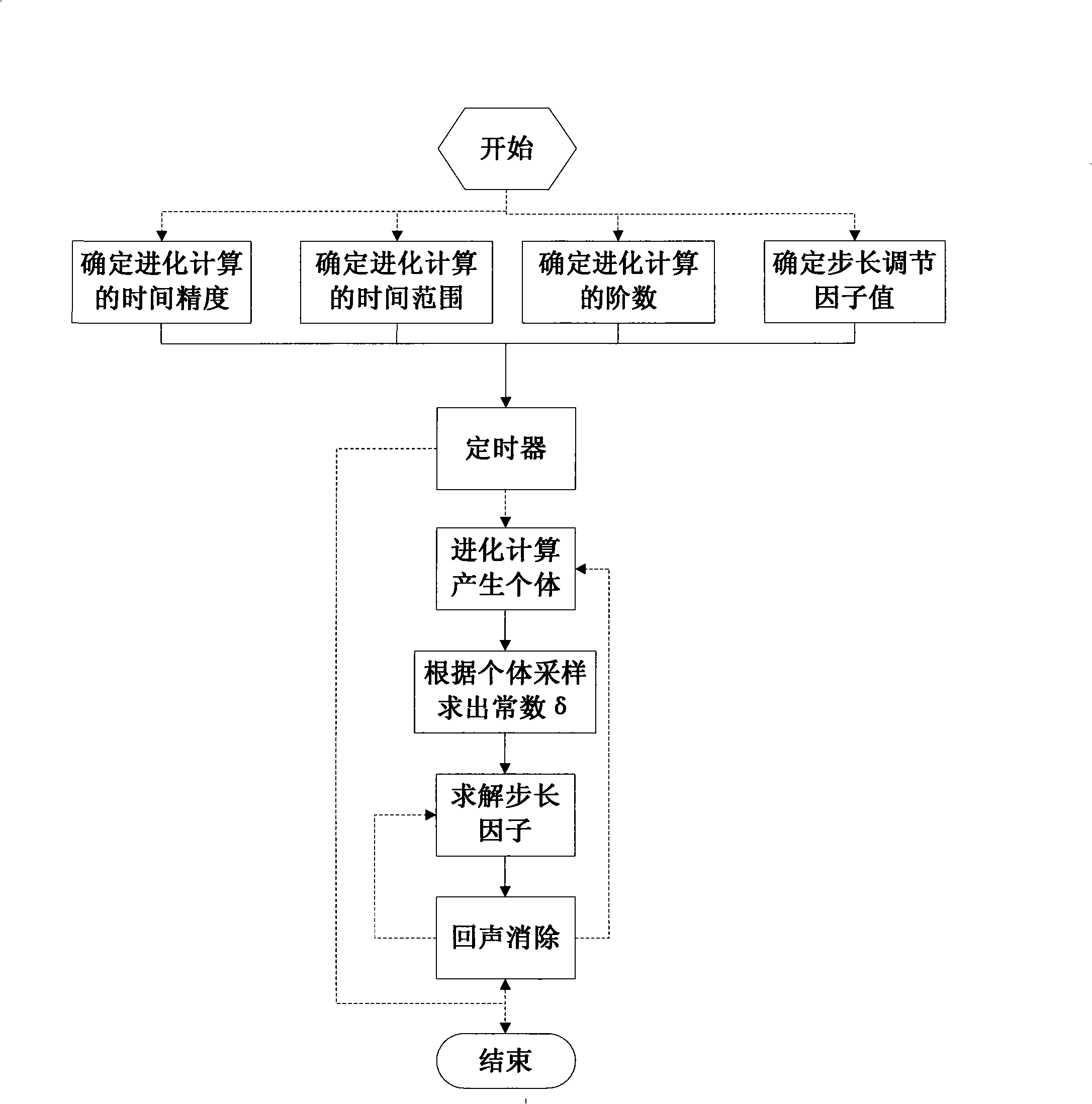
[0061] The basic steps of the adaptive echo cancellation method are as follows: figure 1 shown. figure 1 In , the solid line represents the data flow, and the dashed line represents the control flow. In the basic steps of the adaptive echo cancellation method, first determine the time precision, time range and order of the evolution calculation, and the value of the step size adjustment factor; then, the timer is responsible for finding the constant δ regularly; according to the constant δ, the step can be solved The value of the length factor; finally, according to the step size factor, echo cancellation can be effectively performed according to the echo cancellation formula of the NLMS algorithm.

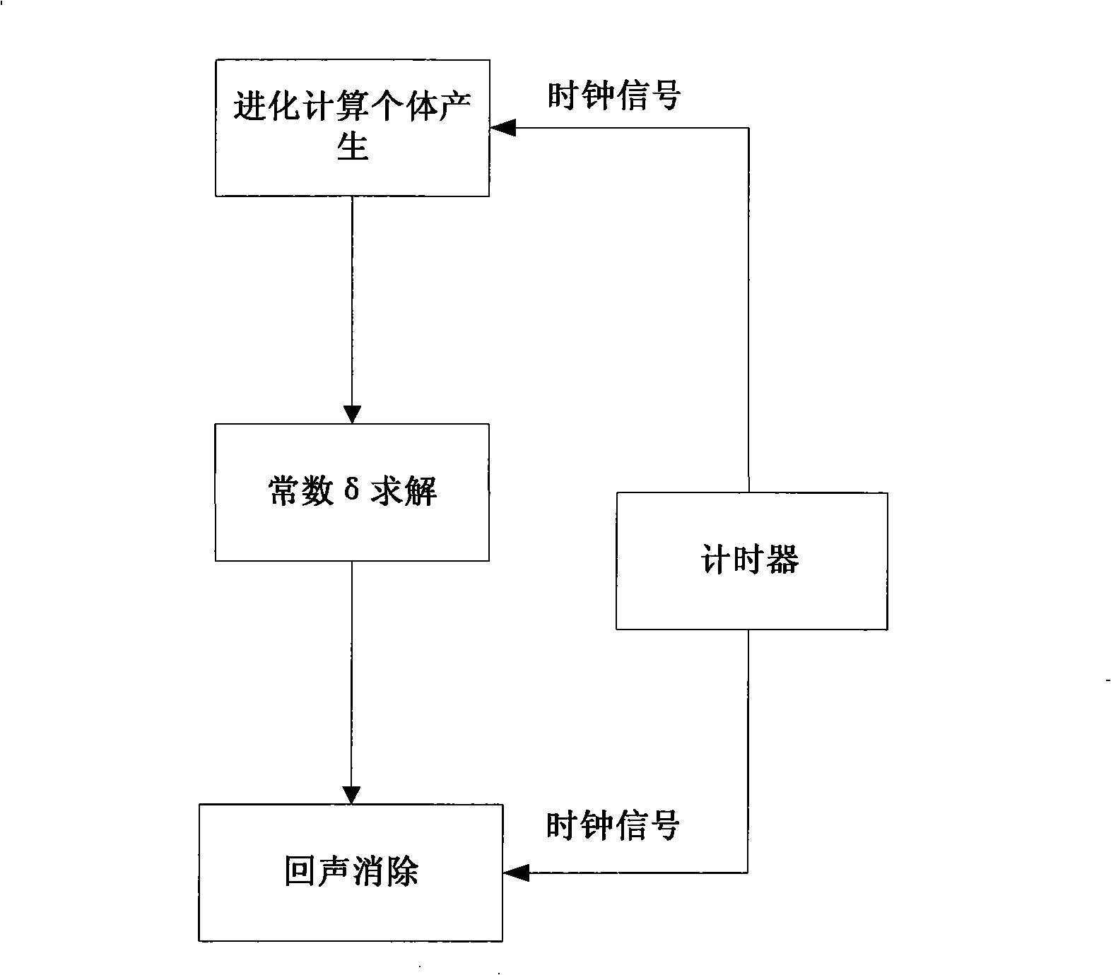
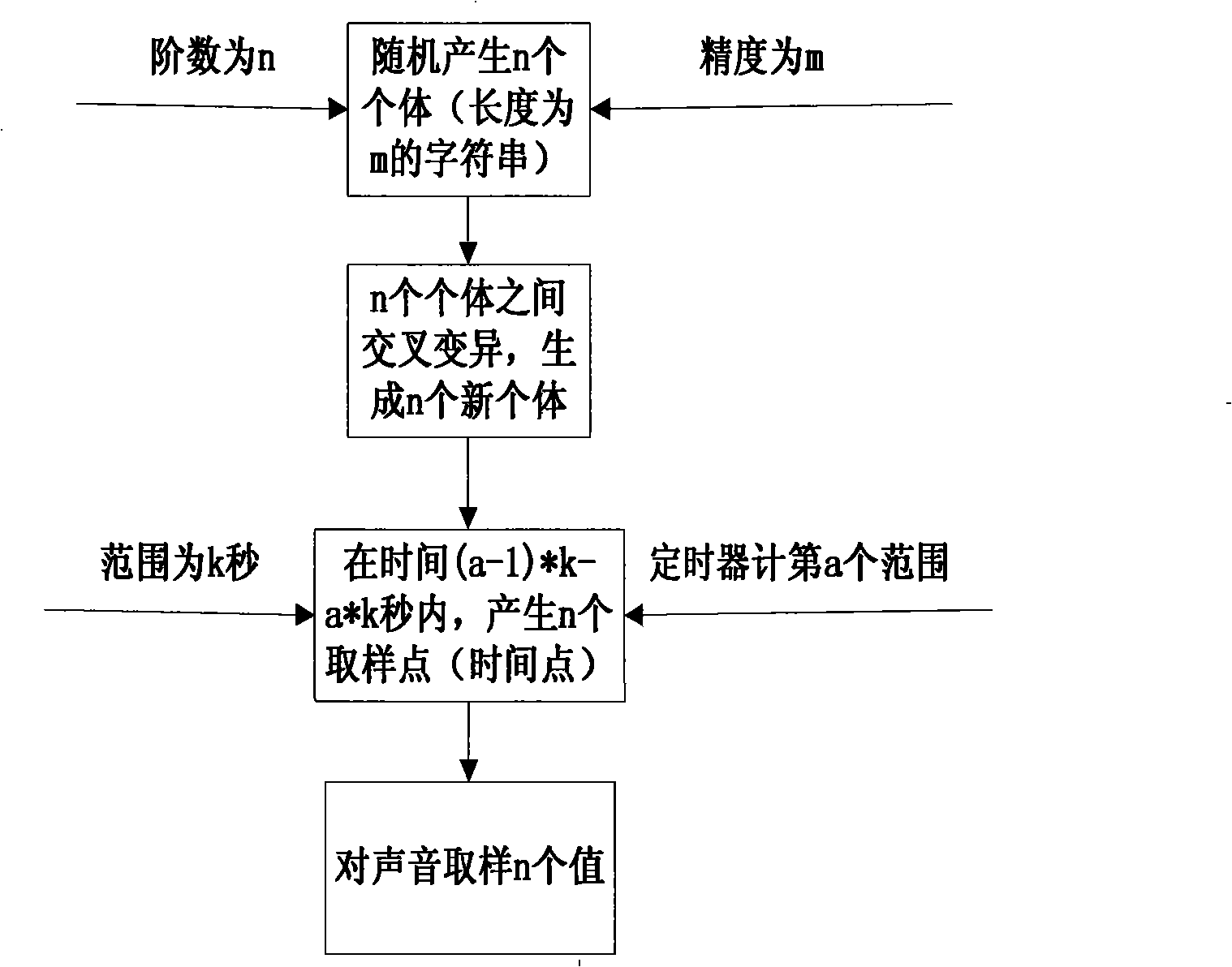
[0062] The core steps to implement the adapted NLMS echo cancellation method are as follows: figure 2 As shown, with the help of the clock signal generated by the time...


PUM


Abstract

The invention discloses an adaptive echo cancellation method. The method introduces the viewpoint of evolutionary computation in the artificial intelligence, simultaneously employs the cross alternative method and the idea of the function global optimization and combines the idea of time driving, so as to effectively solve the problem that the constant Delta value of the parameter of the conventional NLMS algorithm can not be determined, thus improving the performance of the echo cancellation algorithm NLMS.

Description

technical field [0001] The invention relates to the echo elimination technology of mobile communication, in particular to the mobile communication terminal adopting improved NLMS (Normalized Least Mean Square) algorithm to eliminate echo. Background technique [0002] The theory of echo cancellation was first proposed by Bell Laboratories in the early 1960s, followed by a division of the laboratory that introduced the first echo cancellation system in the late 1960s. By the late 1970s, the first commercial analog echo cancellers were developed, which consisted primarily of digital devices with an analog interface to the network. The development of semiconductor technology in the 1980s marked the transition from analog to digital for communication networks. More complex digitally interfaced, multi-channel echo canceller systems were developed to solve the new echo problems associated with long-distance digital telephone systems. This is done by modeling the echo using high-...

Claims


Application Information

Patent Timeline
IPC IPC(8): H04B3/21
Inventor 罗笑南刘宁高成英郑彦树
Owner SUN YAT SEN UNIV
Learn More