
Directly-down back light module unit, LCD device and light tube assembling method

A technology of a liquid crystal display device and a backlight module, which is applied to lighting devices, lighting auxiliary devices, components of lighting devices, etc., and can solve problems such as the unfavorable application of large-sized backlight modules, and the falling off of hooks 250 on the left and right sides. , to achieve the effect of improving production yield and product reliability

Inactive Publication Date: 2008-09-24
INNOLUX CORP
View PDF0 Cites 4 Cited by
  • Summary
  • Abstract
  • Description
  • Claims
  • Application Information

AI Technical Summary

Problems solved by technology

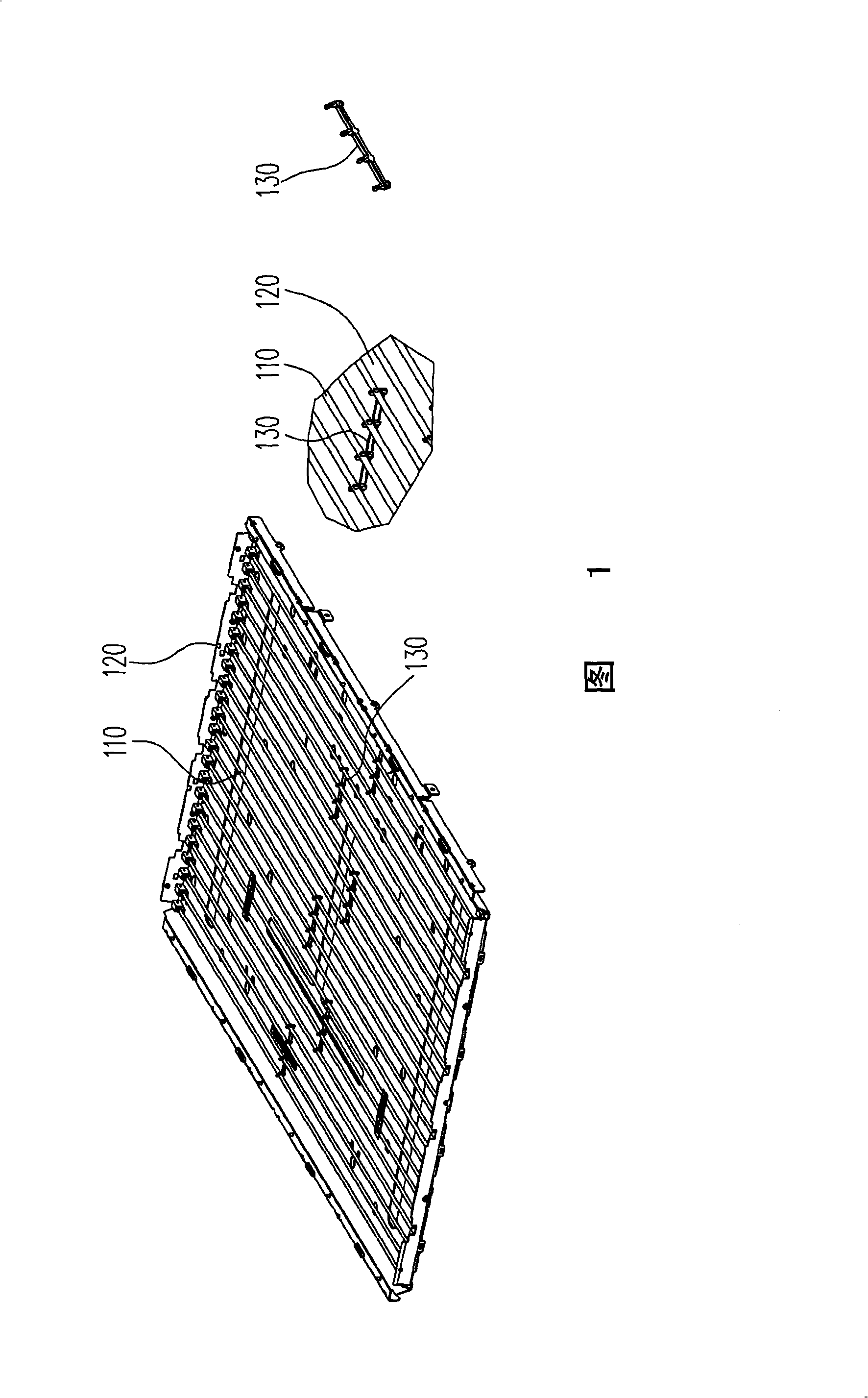
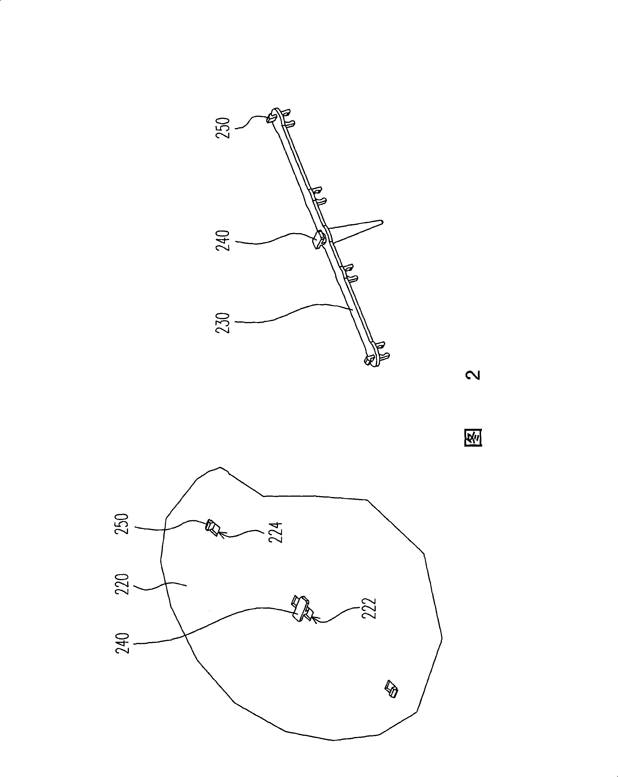
However, this fixing method requires excellent assembly accuracy, otherwise, the hooks 250 on the left and right sides will easily fall off due to poor fit with the holes 224 of the bottom plate 220
In addition, it is necessary to release the restraint of the hook portion 250 from the back of the bottom plate 220 during disassembly, which is not conducive to the application of large-sized backlight modules.
[0006] The above lamp fixing methods all have their insurmountable shortcomings. Therefore, in the existing backlight module assembly technology, there is still an urgent need for a lamp fixing method with high reliability and easy disassembly.

Method used


Image

  • Directly-down back light module unit, LCD device and light tube assembling method
  • Directly-down back light module unit, LCD device and light tube assembling method
  • Directly-down back light module unit, LCD device and light tube assembling method

Examples


Embodiment Construction

[0064] The structure of the direct type backlight module and the installation process of the light tube will be taken as an example below to illustrate the relevant technical points of the present invention.

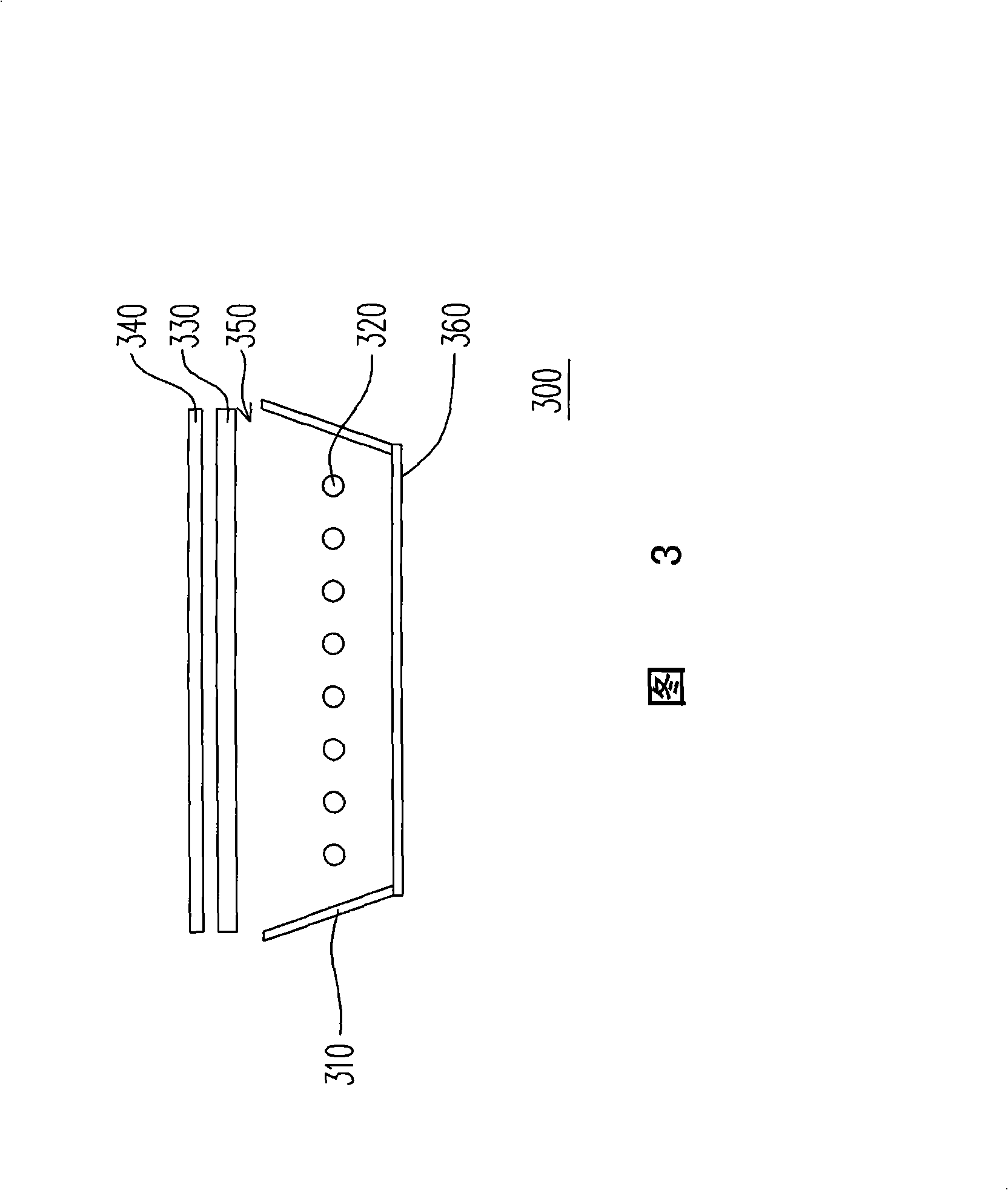
[0065] FIG. 3 is a schematic cross-sectional view of a direct type backlight module of the present invention. Referring to FIG. 3 , the direct-lit backlight module 300 of this embodiment includes a light box 310 and a plurality of light tubes 320 and other components. The light box 310 has an opening 350 and a bottom plate 360 ​​opposite to each other, and the light tube 320 is disposed in the light box 310 . The opening 350 of the light box 310 can optionally be equipped with a diffuser 330 , which functions to improve the distribution of the surface light source provided by the light tube 320 , so that the light output is more uniform. In addition, an optical film 340 may also be disposed on the diffusion plate 330 . Generally speaking, the optical film 340 may includ...


PUM


Abstract

The invention discloses a downright type backlight module which comprises a light box, a plurality of lighting tube fasteners, a plurality of lighting tubes and a diffuser plate. The light box is provided with a soleplate which is opposite to an opening. The soleplate is provided with a plurality of positioning designs, and each positioning design comprises an axle hole and at least one block slot. The lighting tube fasteners are corresponding to the positioning designs and are arranged at the soleplate. Each lighting tube fastener comprises a pivot part, at least one rotary arm, at least one clamp part and at least one positioning part. The lighting tube fasteners can be inserted into the axle hole by the pivot part and can rotate towards the soleplate, so as to ensure that the positioning part enters the block slot to achieve the interference with the block slot. The lighting tubes are arranged inside the light box and are fixed at the clamp part of the lighting tube fasteners, and the diffuser plate is arranged at the opening of the light box. The invention also provides a lighting tube assembling method and a liquid crystal display device which utilizes the downright type backlight module.

Description

technical field [0001] The present invention relates to a light source module and a display device, and in particular to a direct type backlight module, a liquid crystal display device using the direct type backlight module, and a lamp assembly method. Background technique [0002] Liquid crystal displays can be roughly divided into three types: reflective LCD, transmissive LCD and transflective LCD according to the utilization of the light source. Wherein, the transmissive or transflective liquid crystal display is mainly composed of a liquid crystal panel and a backlight module. The liquid crystal panel is composed of two transparent substrates and a liquid crystal layer arranged between the two transparent substrates, and the backlight module is used to provide the light source required by the liquid crystal panel so that the liquid crystal display can achieve display effect. Generally speaking, backlight modules can be divided into two types: direct-type and side-incide...

Claims


Application Information

Patent Timeline
Patent Type & Authority Applications(China)
IPC IPC(8): G02F1/13357G02F1/1333F21S2/00F21V21/10G02F1/1335F21K9/235
Inventor 谢宏明
Owner INNOLUX CORP
Learn More