
Sliding-type constant velocity universal joint

A constant velocity universal joint, sliding technology, applied in the direction of connection, centrifugal force-resistant rotating parts, elastic couplings, etc., can solve the problems of compactness, weight increase and other problems that are light enough

Active Publication Date: 2008-09-17
NTN CORP
View PDF4 Cites 10 Cited by
  • Summary
  • Abstract
  • Description
  • Claims
  • Application Information

AI Technical Summary

Problems solved by technology

In the DOJ type having eight torque transmission balls, the guide force of the balls is ensured, and the optimal value of the offset amount of the center of the inner and outer spherical surfaces of the bearing cage is proposed to form the wall thickness of the bearing cage to the necessary minimum. But since there are eight balls, the maximum action angle can only be 25°
[0010] On the other hand, when the maximum operating angle exceeds 25° among the conventional six balls, the outer diameter of the outer ring Since it becomes about 1 size larger, it causes a considerable increase in weight
Therefore, among the joints in which the shape of the contact ellipse between the groove and the ball is improved (Patent Document 1), or the joint in which the groove shape is improved by combining circular contact and inclined contact (Patent Documents 2 and 3) Among them, in a DOJ with six balls, it was found that it is difficult to achieve a high angle of action while achieving a sufficiently lightweight compact

Method used


Image

  • Sliding-type constant velocity universal joint
  • Sliding-type constant velocity universal joint
  • Sliding-type constant velocity universal joint

Examples


Embodiment 1

[0032] The DOJ of the present invention does not only have a contact angle of 30° to 35°, but simply forming the contact angle to 30° to 35° will cause an increase in groove surface pressure and a decrease in durability. Therefore, the internal specifications are also changed for other than the contact angle. Table 1 compares the embodiment of the product of the present invention and the conventional product by 5 items. In the present invention, it was confirmed that the DOJ with six balls achieves a size reduction of 3% or more compared to the conventional product.

[0033] 【Table 1】

[0034] project

Product of the present invention

Existing goods

1

(ball diameter) / (outer ring diameter)

0.21~0.25

0.21~0.25

2

(Pitch circle diameter of ball) / (outer ring diameter)

0.64~0.68

0.64~0.68

3

groove contact angle

30~35°

35~40°

4

Groove Contact Ratio

1.02~1.08

1.04~1....


PUM


Abstract

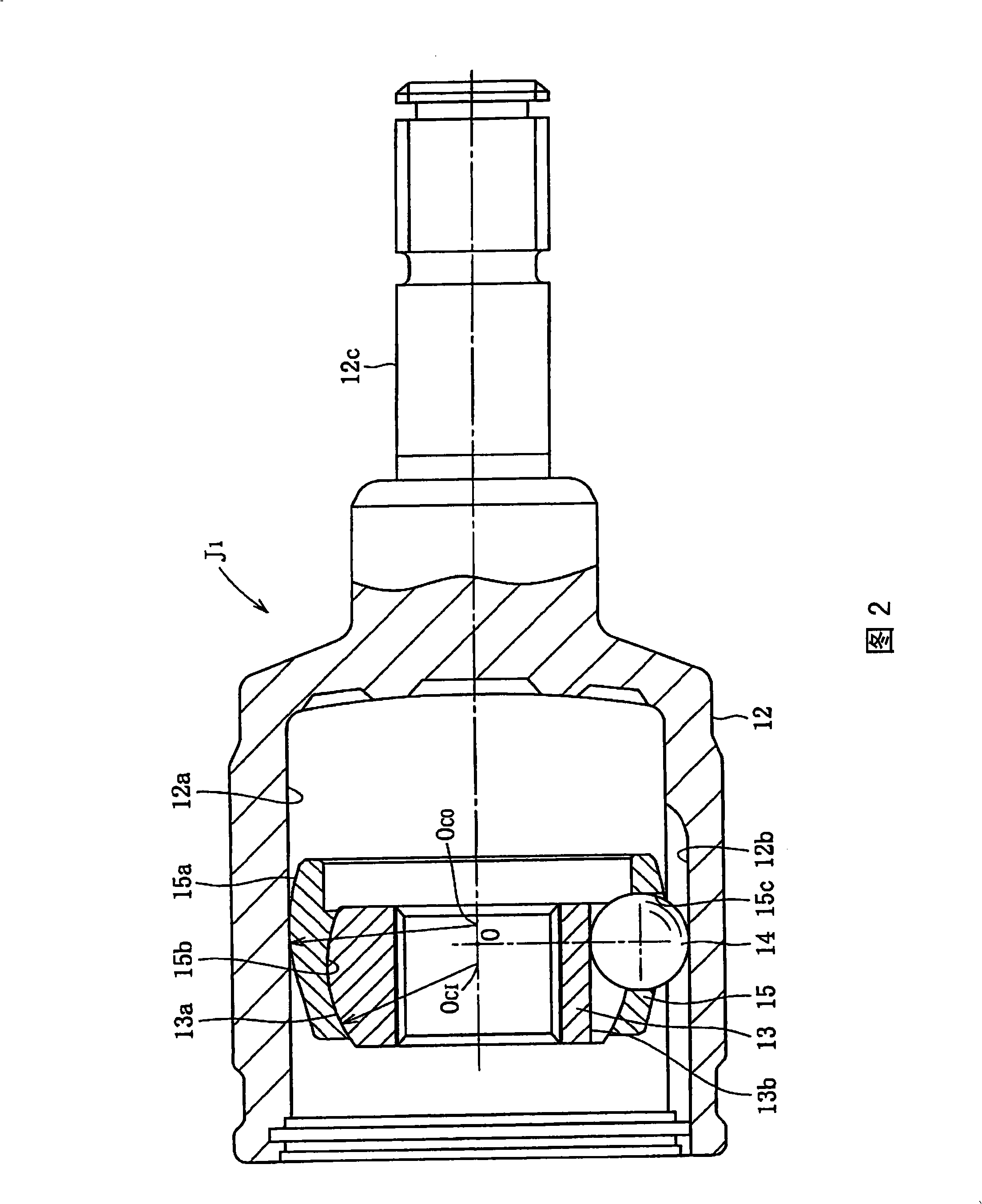
The present invention provides a light and compact slide-type constant velocity universal joint that can have a maximum operating angle of 30 DEG or more through optimization of a ball contact angle relative to ball grooves, a ball contact ratio, and a cage offset amount. The present invention is the slide-type constant velocity universal joint including an outer ring 12 in which six linear ball grooves 12b are formed on a cylindrical inner circumferential surface 12a in an axial direction, an inner ring 13 on which six linear ball grooves 13b are formed on a spherical outer circumferential surface 13a in the axial direction and a connecting hole for connecting a shaft is formed in a center section, six torque transmission balls 14 disposed on ball tracks formed by a pair composed of the a ball groove 12b on the outer ring 12 and a ball groove 13b on the inner ring 13, and a cage 15 having pockets 15c for storing the torque transmission balls 14, a convex spherical outer circumferential surface 15a that is in contact with and guided by the inner circumferential surface 12a of the outer ring 12, and a concave spherical inner circumferential surface 15b that is in contact with and guided by the outer circumferential surface 13a of the inner ring 13 and in which a spherical surface center O C0 of the outer circumferential surface 15a and a spherical surface center O CI of the inner circumferential surface 15b are offset to opposite sides of a pocket center O in the axial direction. In the slide-type constant velocity universal joint, a ratio of ball diameter to outer ring outer diameter is 0.21 to 0.25, a ratio of ball pitch diameter to outer ring outer diameter is 0.64 to 0.68, a contact angle of the ball groove is 30 DEG to 35 DEG , a contact ratio of the ball groove is 1.02 to 1.08, and a ratio of cage offset amount to ball pitch diameter is 0.07 to 0.09.

Description

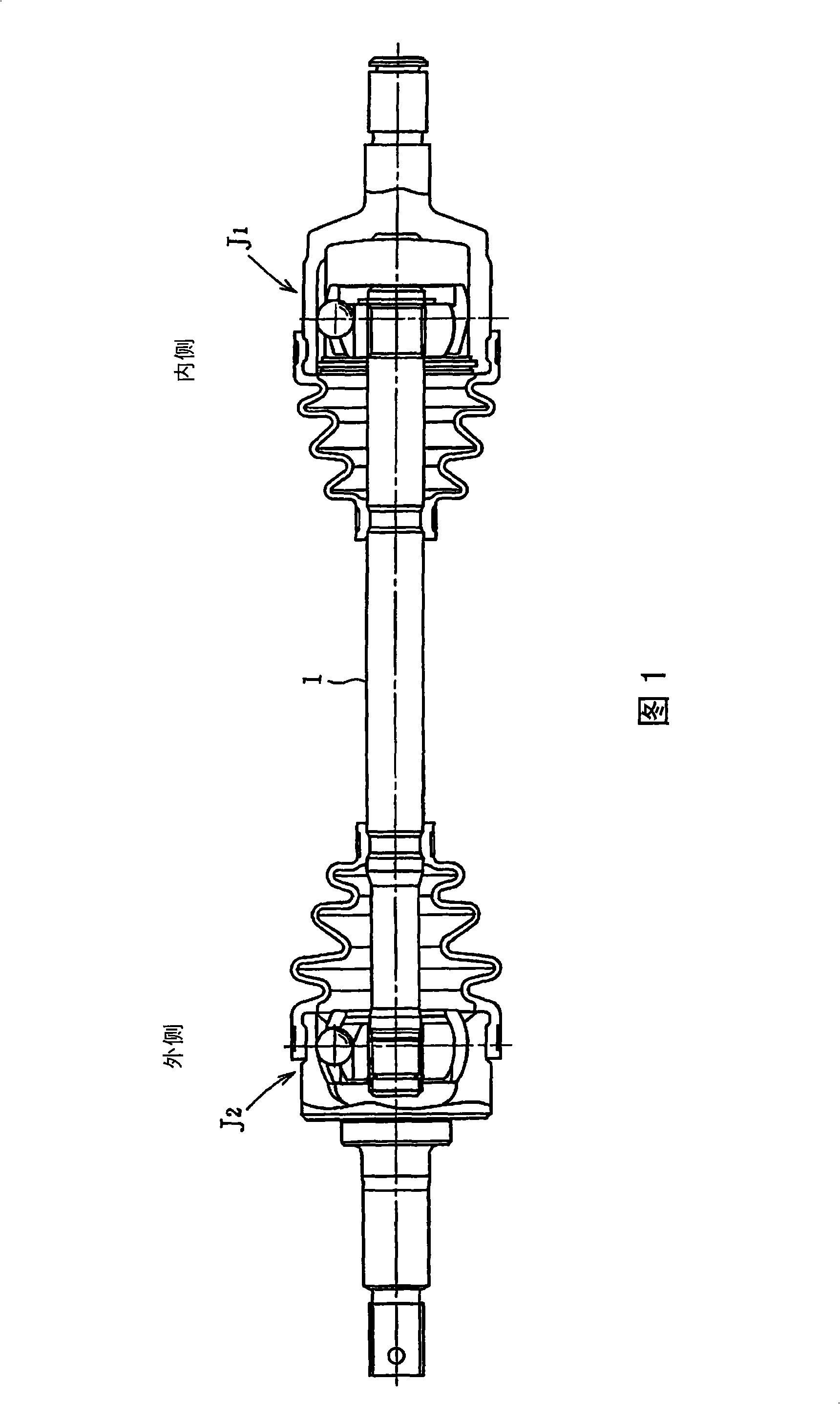
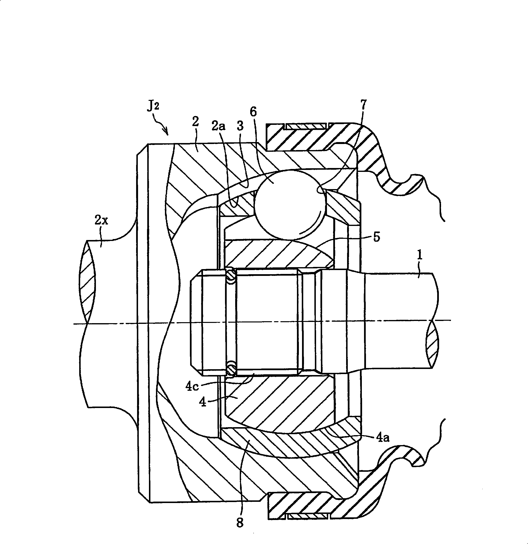
technical field [0001] The present invention relates to a sliding type constant velocity universal joint used in automobiles or various industrial machines, and more particularly to a method for optimizing the ball contact angle, ball contact ratio, and bearing cage offset with respect to the inner and outer ring grooves. This is a slide-type constant velocity universal joint that has been optimized to achieve both a high angle of action and light weight and compactness. Background technique [0002] The constant velocity universal joint has a fixed type that allows only angular displacement between two shafts, and a sliding type that allows angular displacement and axial displacement (plunging). Both forms have rollers or balls as torque transfer elements. Slip-type constant velocity universal joints are used in propeller shafts and drive shafts in the automotive field. The drive shaft typically has a sliding constant velocity universal joint on the inboard and a fixed co...

Claims


Application Information

Patent Timeline
IPC IPC(8): F16D3/227F16D3/2245
CPCF16D2003/22309F16D2003/22303F16D3/2237F16D3/227Y10S464/906Y10T403/32057
Inventor 小林正纯山崎起佐雄
Owner NTN CORP
Learn More