Turbocharger cleaning arrangement

A technology of turbo compressors and equipment, applied in mechanical equipment, gas turbine devices, machines/engines, etc., can solve problems such as economic losses in power production, and achieve the effect of easy equipment and economically feasible

Active Publication Date: 2008-09-10
WARTSILA FINLAND OY
View PDF1 Cites 13 Cited by
  • Summary
  • Abstract
  • Description
  • Claims
  • Application Information

AI Technical Summary

Problems solved by technology

For example in the case of engines in power plants, a drop in electricity production due to turbine cleaning can lead to serious economic losses

Method used


Image

  • Turbocharger cleaning arrangement
  • Turbocharger cleaning arrangement
  • Turbocharger cleaning arrangement

Examples


Embodiment Construction

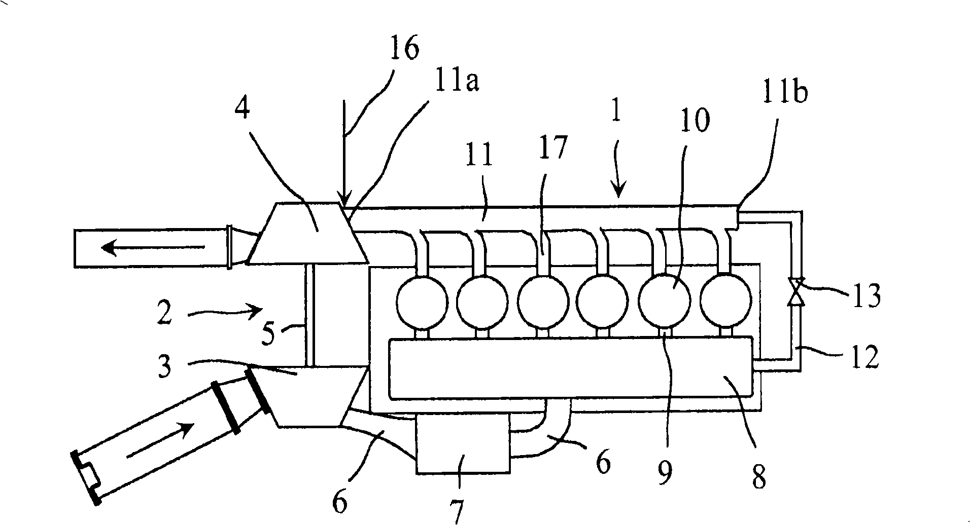
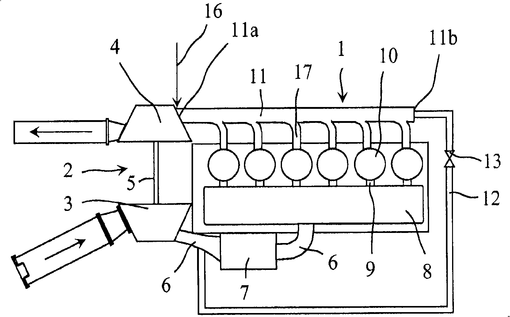
[0019] Figure 1 to Figure 3 A piston engine 1 provided with a turbo compressor 2 is shown. The turbo compressor 2 includes a compressor 3 and a turbine 4 interconnected by a drive shaft 5 . The drive shaft 5 is attached to the casing of the turbocompressor 2 by a bearing system. The task of the compressor 3 is to supply pressurized air to the engine 1 to provide combustion air for fuel. The compressor 3 comprises a rotatable rotor provided with blades to pressurize combustion air for delivery to the engine 1 . The flow space 6 is fitted on the high pressure side of the compressor 3 , ie between the compressor 3 and the combustion space of the engine cylinder 10 , to deliver pressurized combustion air to the cylinder 10 . The flow space 6 is provided with a heat exchanger 7 to cool or heat the combustion air. In addition, the flow space 6 comprises a charge air receiver 8 located behind the heat exchanger 7 in the flow direction of the combustion air. The flow space 6 als...


PUM


Abstract

An arrangement in connection with a piston engine (1) provided with a turbocompressor (2), which arrangement comprises a flow duct (6) for conveying combustion air pressurized by a compressor (3) to cylinders (10) of the piston engine (1), an exhaust gas duct (11) for conveying exhaust gas from the piston engine (1) to a turbine (4), and means (16) adapted in conjunction with the turbine (4) for feeding a cleansing agent to the turbine (4). There are feeding means (12; 14) arranged in connection with the exhaust gas duct (11) for introducing air and / or water into the exhaust gas duct (11) for cooling the exhaust gas.

Description

technical field [0001] The invention relates to an arrangement related to a piston engine provided with a turbo compressor. [0002] The invention also relates to a method related to a piston engine provided with a turbocompressor. Background technique [0003] The use of turbo compressors to increase the output of an engine is known in the art of engine technology. The turbo compressor includes the compressor section through which pressurized combustion air is introduced into the engine. In addition, turbo compressors include a turbine section for driving the compressor. Exhaust gas from the engine is directed to a turbine, which converts the energy of the exhaust gas into drive power for the compressor. Carbon deposits form on those parts of the turbine that come into contact with the exhaust. Carbon buildup is particularly severe when heavy fuel oil is used as fuel. The temperature of the turbine surfaces that come into contact with the exhaust gas increases substant...

Claims


Application Information

Patent Timeline
Patent Type & Authority Applications(China)
IPC IPC(8): F01D25/00F02C6/12F02B37/16F02B39/16F02M
CPCF02B39/16F05D2220/40F01N3/04Y02T10/144F02B37/16F01D25/002F05D2260/607Y02T10/20Y02T10/12F01N3/05F02B77/04F02C7/1435F02B39/00F02B29/04F01D25/00
Inventor A·贾维
Owner WARTSILA FINLAND OY
Why Eureka
Try Eureka