Automatic gain control circuit
A technology of automatic gain control and gain control signal, which is applied in the direction of gain control, improvement of control circuit for reducing distortion, amplification control, etc. It can solve problems such as discomfort and strong hearing, and achieve the effect of excellent automatic gain adjustment circuit
- Summary
- Abstract
- Description
- Claims
- Application Information
AI Technical Summary
Problems solved by technology
Method used
Image

Examples
no. 1 approach
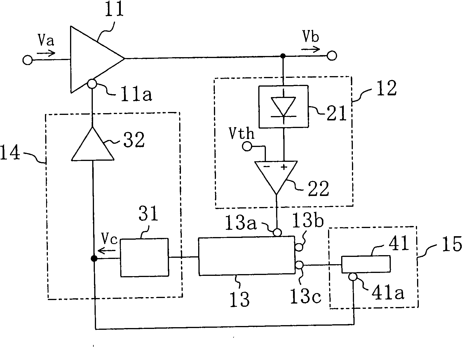
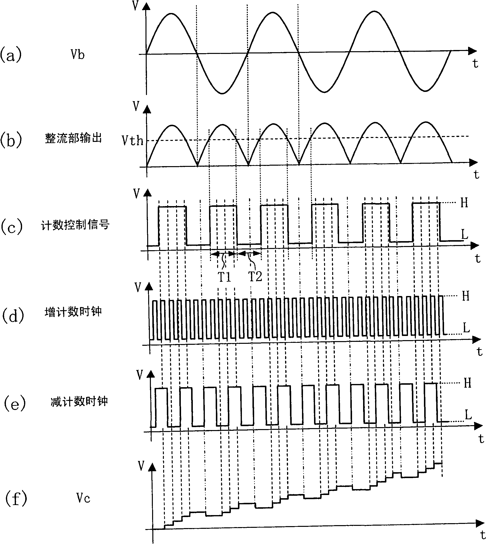
[0062] A first embodiment of the present invention will be described with reference to the drawings. figure 1 A circuit configuration of an automatic gain control (AGC) circuit according to the first embodiment of the present invention is shown. like figure 1 As shown, the AGC circuit of the first embodiment controls the gain of the variable gain amplifier 11 according to the value of the input signal Va. The gain of the variable gain amplifying section 11 changes according to a gain control signal applied to the gain control terminal 11a. The output signal Vb of the variable gain amplifier 11 is input to the count control signal generator 12 . The count control signal generating unit 12 includes a rectifying unit 21 that detects and rectifies the output signal of the variable gain amplifier 11 , and a threshold voltage comparing unit 22 that compares the output of the rectifying unit 21 with a threshold voltage.
[0063] The output of the count control signal generator 1...
no. 2 approach
[0090] Next, a second embodiment of the present invention will be described with reference to the drawings. Figure 11 The circuit configuration of the AGC circuit of the second embodiment is shown. The output of the variable gain amplifier 11 whose gain changes according to the voltage applied to the gain control terminal 11 a is input to the count control signal generator 12 . The count control signal generating unit 12 includes a rectifying unit 21 that detects and rectifies the output signal of the variable gain amplifier 11 , and a threshold voltage comparing unit 22 that compares the output of the rectifying unit 21 with a threshold voltage.
[0091] The output of the count control signal generator 12 is connected to the first count control terminal 16 a of the first up-down counter 16 . In the first up-down counter 16, when the voltage of the first count control signal applied to the first count control terminal 16a is at a high level, counting up is performed accordin...
no. 3 approach
[0112] Next, a third embodiment of the present invention will be described with reference to the drawings. Figure 17 The circuit configuration of the AGC circuit according to the third embodiment of the present invention is shown. Figure 17 in, right with Figure 13 The same components are assigned the same symbols and descriptions thereof are omitted.
[0113] like Figure 17 As shown, the AGC circuit of this embodiment generates a gain control signal by amplifying the output Vc of the first D / A converter 33 .
[0114] By switching the supply source of the gain control signal, the waveform of the gain control signal is deformed, and a signal of a frequency not originally input may be generated. Furthermore, it may occur that switching noise is generated by a switching circuit for switching signals, a waveform of a gain control signal is deformed, and an abnormal signal is generated. However, since the AGC circuit of the present embodiment does not require an output sele...
PUM
 Abstract
Description
Claims
Application Information
 - R&D
- Intellectual Property
- Life Sciences
- Materials
- Tech Scout
- Unparalleled Data Quality
- Higher Quality Content
- 60% Fewer Hallucinations
Browse by: Latest US Patents, China's latest patents, Technical Efficacy Thesaurus, Application Domain, Technology Topic, Popular Technical Reports.
© 2025 PatSnap. All rights reserved.Legal|Privacy policy|Modern Slavery Act Transparency Statement|Sitemap|About US| Contact US: help@patsnap.com