
Polarization type LED luminous tube

An LED light-emitting tube and polarizing technology, which is applied to the semiconductor devices of light-emitting elements, light sources, point light sources, etc., can solve the problems of uneven luminous intensity distribution curve, difficult control, high mold cost, etc. Energy saving effect, low cost, power reduction effect

Inactive Publication Date: 2008-09-10
SHANGHAI SANSI ELECTRONICS ENG +1
View PDF1 Cites 9 Cited by
  • Summary
  • Abstract
  • Description
  • Claims
  • Application Information

AI Technical Summary

Problems solved by technology

Due to the small shape of the bracket and the radiation cup, this design not only has high mold cost, but also requires too high precision and is very difficult to control. Therefore, it is found in use that the luminous intensity distribution curve is not smooth, uneven, and the light source Waste phenomenon, therefore, this practice was gradually phased out later

Method used


Image

  • Polarization type LED luminous tube
  • Polarization type LED luminous tube
  • Polarization type LED luminous tube

Examples


Embodiment Construction

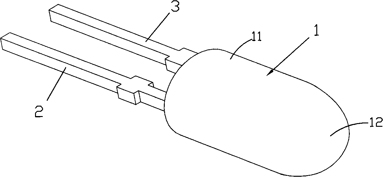
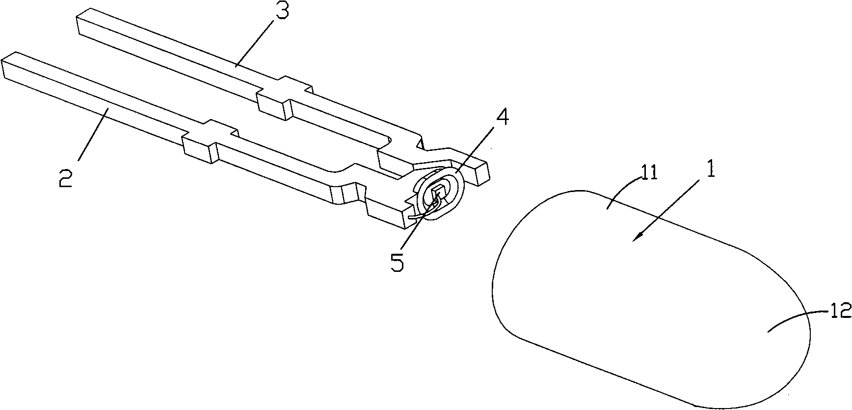
[0022] see figure 1 ~ Fig. 5, an embodiment of the polarized LED luminous tube of the present invention, the LED luminous tube includes two brackets 2, 3 connected by lead wires, a reflective cup 4 placed at the front ends of the brackets 2, 3 and a reflective cup 4 The chip 5 at the bottom, and the encapsulation lens 1 encapsulating the brackets 2, 3 and the reflective cup 4;

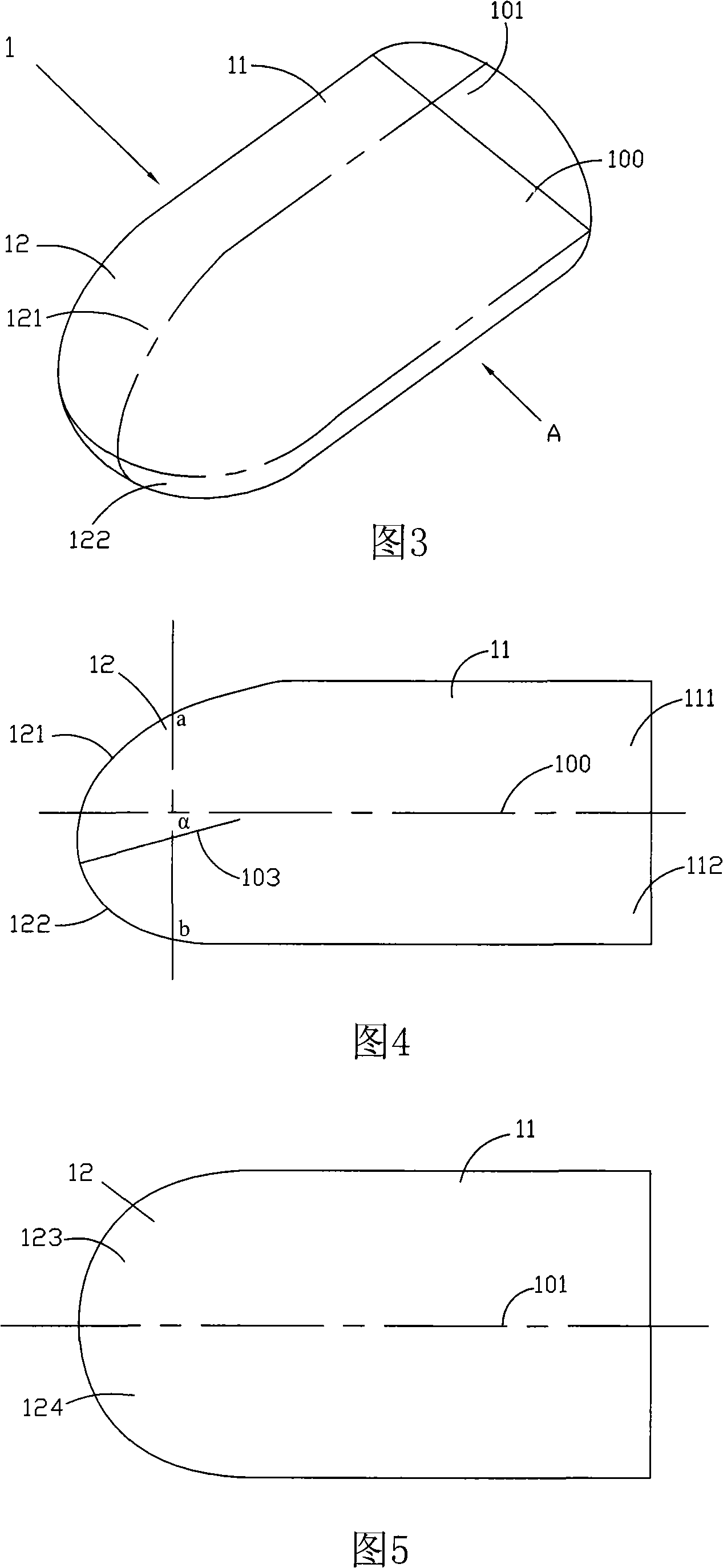
[0023] The encapsulation lens 1 includes a cylindrical portion 11 and a convex portion 12. The plane where the centerlines of the brackets 2 and 3 are located is a horizontal reference plane 100. The two curved surfaces 121, 122 are asymmetrical; the vertical plane 101 where the axial center line of the cylinder part 11 is located is the vertical reference plane 101, and the two left and right curved surfaces 123, 124 of the convex part 12 are symmetrical with the vertical reference plane 101 as the boundary. and, the curvature of a certain point a on the upper curved surface 121 of the convex portion...


PUM

PropertyMeasurementUnit
Tilt angleaaaaaaaaaa

Abstract

The invention relates to a polarizing type LED luminotron, comprising a bracket, a reflecting cup, a chip and a packaging lens which packages the bracket and the reflective cup, wherein, the packaging lens comprises a column part and a convex part; a plane where the center line of the bracket is positioned or a plane which is parallel to the plane where the center line of the bracket is taken as a horizontal reference plane; an upper curved surface and a lower curved surface of the convex part of the packaging lens, taking the reference plane as a boundary, are unsymmetrical; a plane which is vertical to the horizontal reference plane and passes through an axial center line of the column part is taken as a vertical reference plane; a left curved surface and a right curved surface of the convex part, taking the vertical reference plane as a boundary, are symmetrical; in addition, the curvature of one point on the upper curved surface of the convex part taking the horizontal reference plane as the boundary is less than the curvature of a point which is positioned on the lower curved surface and corresponding to the point on the upper curved surface vertically. The invention adopts unsymmetrical design through changing the curvature of curved surfaces of a transmission body, so that an optical axis and a mechanical axis are separated in the vertical direction, visual angles of luminous rays are deviated in the vertical direction, a viewer can watch pictures facing to the optical axis direction, thereby achieving optimization of the brightness and the effect.

Description

technical field [0001] The invention relates to the field of LED light-emitting diodes, in particular to a polarized LED light-emitting tube with an inclined optical axis. Background technique [0002] With the gradual popularization and application of LED light-emitting diodes in the field of lighting and display, its advantages in energy saving, high efficiency and environmental protection are increasingly recognized by people. At the same time, people also adopt various methods to further improve the light efficiency and performance of LEDs. [0003] The usual LED light-emitting diode structure includes two metal brackets as positive and negative pins, one of which has a bowl-shaped reflective cup on the upper part of the bracket, the chip is placed at the bottom of the reflective cup, and the metal bracket and the outside of the reflective cup are covered with epoxy resin. The finished lens is encapsulated. The light emitted by the chip is refracted by the lens and refl...

Claims


Application Information

Patent Timeline
IPC IPC(8): F21V5/04H01L33/00F21Y101/02F21Y115/10H01L33/48H01L33/58
Inventor 程德诗周士康王彪章琴华
Owner SHANGHAI SANSI ELECTRONICS ENG
Learn More