Novel high voltage combined independent electronic type current, voltage mutual inductor

A technology of voltage transformers and current transformers, applied in the direction of inductors, transformers, instruments, etc., can solve problems such as cost reduction, achieve the effect of eliminating optical power supply, reducing external distributed capacitance and stray capacitance, and reducing influence

Inactive Publication Date: 2008-09-03
武汉格蓝若智能技术股份有限公司
View PDF0 Cites 20 Cited by
  • Summary
  • Abstract
  • Description
  • Claims
  • Application Information

AI Technical Summary

Problems solved by technology

[0007] The invention provides a new combined independent electronic current and voltage transformer, which completely overcomes the defects of the above-mentioned electronic current and voltage transformers, wherein the electronic current transformer adopts the insulation structure of an inverted gas-insulated current transformer, so that the current Both the measuring coil and the signal modulation circuit board are located at the ground potential, so the ordinary power supply can be directly powered by a cable, and the optical power supply is no longer needed, which greatly improves the reliability; the electronic voltage transformer uses the primary conductor of the inver

Method used


Image

  • Novel high voltage combined independent electronic type current, voltage mutual inductor
  • Novel high voltage combined independent electronic type current, voltage mutual inductor
  • Novel high voltage combined independent electronic type current, voltage mutual inductor

Examples


Embodiment Construction

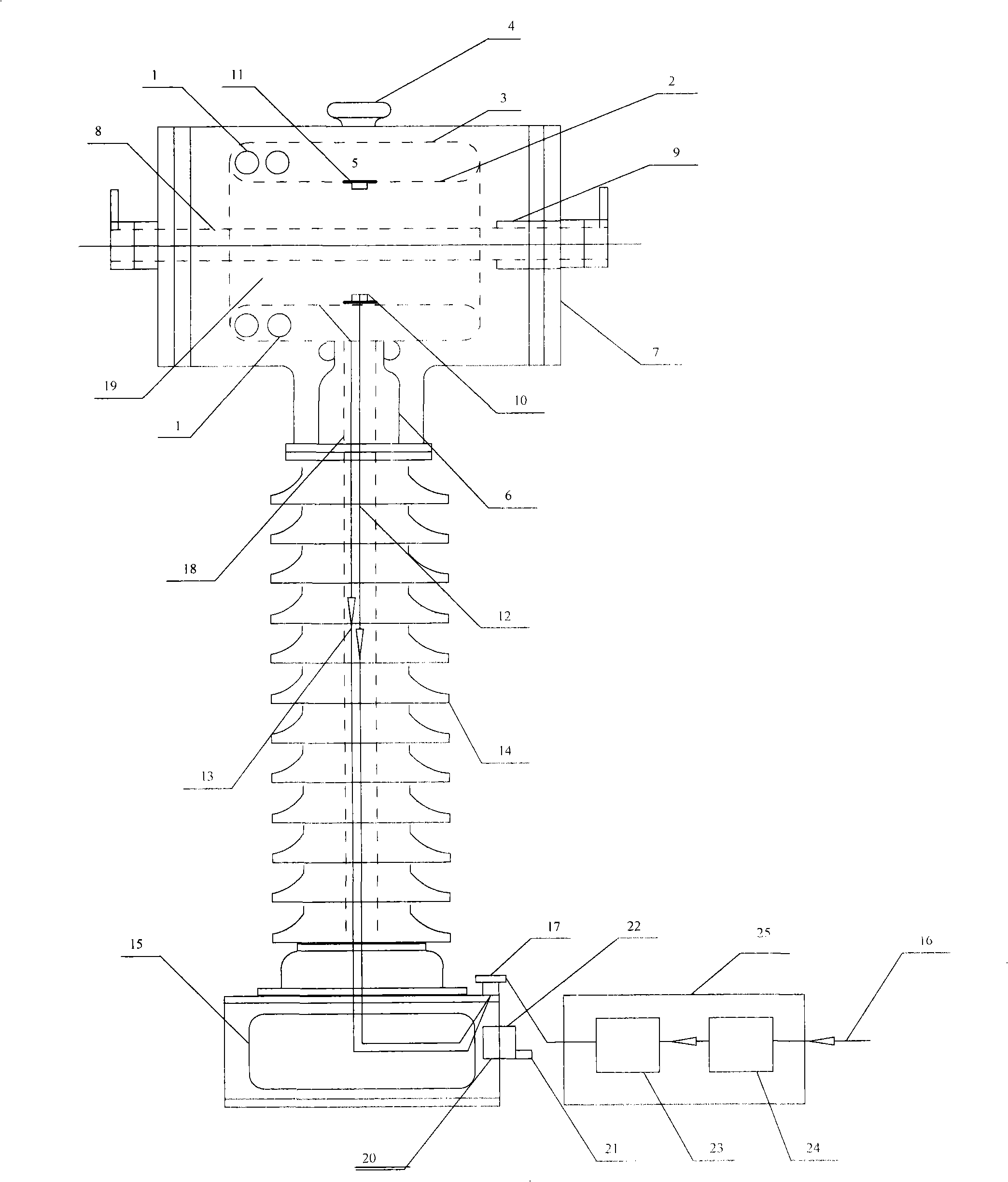
[0030] The overall structure of the present invention is as Figure 1a As shown, the structure of an inverted gas insulated current transformer is adopted. The current secondary winding 1 is placed in the ground potential shielding cylinder 5 formed by the inner layer 2 of the double-layer shielding cylinder and the outer layer 3 of the double-layer shielding cylinder, and is fixed on the housing 7 via the supporting insulator 6, and the primary conductor 8 traverses the current horizontally. The secondary winding 1 is fixed on the housing 7. The left end of the primary conductor 8 is electrically connected to the housing 7, and the right end is electrically insulated from the housing 7 through a sealing ring and an insulating sleeve 9. A rupture disc 4 is also installed on the upper part of the housing 7 , Can be used to release too high SF 6 The air pressure protects the casing 7 and the insulating sleeve 14; the metal cylindrical ring 10 fixed on the inner surface of the inner ...


PUM


Abstract

The present invention relates to novel high pressure combination independent electronic type current, voltage transformer, which includes inverted vertical SF6 gas insulation current mutual-inductor, electronic voltage mutual inductor, signal conditioning modulation circuit and direct current supply, the conventional iron-core coil inverted vertical SF6 gas insulation current mutual-inductor of the conventional iron-core coil is taken placed by hollow coil or low power iron-core coil and hollow coil, the insulated low-voltage electric pole is fixed by using the same insulator of current transformer at inner layer of the double-layer shielding barrel, and the low-voltage electric pole has same center with the primary conductor and double-layer shielding barrel, a conducting wire is fixed or welded at the low-voltage electric pole and the inner layer of the double-layer shielding barrel respectively, the output lead of the current secondary winding and the output conducting wire of the voltage transformer secondary sensing connect with the current of the signal conditioning modulation circuit and the input terminal of the electric voltage channel respectively, the direct current supply connects with the signal conditioning modulation circuit. The present invention adopts SF6 as main insulation with simple insulation structure and high insulating intensity, and overcoming defect of electronic type current and voltage transformer and reducing cost greatly.

Description

Technical field [0001] The invention relates to a new high-voltage combined independent electronic current and voltage transformer, which is used for current and voltage conversion in a high-voltage environment of open substations for measurement, protection and monitoring. The invention is suitable for 110kV and above high-voltage power system. Background technique [0002] Electronic current and voltage transformers have obvious advantages because their sensing principles are completely different from traditional iron core transformers. [0003] From the classification of measurement principles, according to the IEC standard, electronic current transformers include optical current transformers (also known as passive type), air-core current transformers (also known as Rogowski coils, active type) and low-power current transformers. There are three types of transformers; electronic voltage transformers include two types: optical voltage transformers and voltage divider type volta...

Claims


Application Information

Patent Timeline
IPC IPC(8): H01F38/34H01F27/36G01R15/00
Inventor 窦峭奇
Owner 武汉格蓝若智能技术股份有限公司
Why Eureka
Try Eureka